Boss 5.4L V8
Information on the Ford Boss 5.4L V8 based on the Modular platform from the Australian Ford Falcon XR8
General Information
| Cylinders | 8 |
| Displacement | 5408 cc / xx ci |
| Firing Order | 1,3,7,2,6,5,4,8 |
| Cylinder Orientation |
CAN
This vehicles uses CAN bus for various devices throughout the vehicle. This can include the dashboard, ABS, and Body Control. Support has been added for some models to the Elite 2500.
Model Variants
There are a number of variants of the Boss engine.
Boss 260
DOHC 4V per Cylinder, 9.5:1 compression, 6000 rpm limit
Boss 290 FG XR8
Balanced crank, different pistons rods and bearings, 10.5:1 compression, thicker gudgeon pin, stronger head bolts, better head gaskets, stainless valves, higher lift cams, larger fuel rails and higher flowing injectors, extra knock sensor,
Boss 302 FPV BF
As 290 with new cams, 10.8:1 compression
Boss 315 FPV FG
New cams, 11.0:1 compression, twin plate throttle body, RPM Limit increased to 6500rpm
Boss 302 FPV FG
As 315 with RPM Limit dropped back to 6000rpm
Barra 220 3V VVT
Not covered by this guide. 3V per cylinder with intake variable cam timing.
Barra 230 3V VVT
Increased compression ration
Sensor Information
Crank/Cam Sensor
This engines uses a Crank Position Sensor and a Cam Position Sensor. The crank trigger uses a 36x tooth wheel with a 1x tooth missing gap and is located inside the timing cover.
The cam sensor has a single tooth.
Crank Sensor
A Reluctor crank position sensor is used. This is located on the left hand side of the crank pulley.
Reluctor Wiring
| Pin | Description | Haltech Connection (Trigger 4-core) |
| 1 | Reluctor + | Yellow |
| 2 | Reluctor - | Green |
Cam Sensor
A Reluctor cam sensor is used. This is located on the front of the RHS cylinder head as viewed from the front of the engine.
Reluctor Wiring
| Pin | Description | Haltech Connection (Home 4-core) |
| 1 | Reluctor + | Yellow |
| 2 | Reluctor - | Green |
Trigger Configuration
Ignition Coils and Igniter
The ignition coils on this engine require an external igniter module. The OEM ECU has the igniters built in, and so do does the Haltech Elite Pro ECU. For use with an Elite 2500 a Haltech HPI 6 igniter module is a good choice for this.
| Pin | Description |
| 1 | Signal |
| 2 | 12V+ Switched |
Haltech HPI Igniter
A Haltech HPI 8 igniter is recommended for this application.
See the Haltech HPI Quick Start Guide for wiring information on these igniters.
Dwell Time
Dwell data can be imported from the Barra base map.
DBW Throttle System
This engine uses a single Drive By Wire throttle body.
BA-BF Throttle Wiring
FG Throttle Wiring
DBW Accelerator Pedal Position Sensors Connection
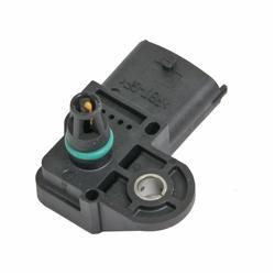
MAP Sensor
This vehicle comes with a T-MAP sensor that also has an Air Temperature Sensor included.
BA-BF
FG
If preferred you can use the internal MAP sensor that comes with your Elite ECU. For higher boost levels an external MAP sensor should be used instead, connected to a spare AVI.
Idle Valve
This engine uses the Drive By Wire Throttle to control idle speed.
Coolant (Cylinder Head) Temperature
Wiring is not polarity sensitive
| Pin | Haltech Connection |
| 1 | Any Spare AVI* |
| 2 | Signal Ground |
An AVI with a selectable Pullup should be used. If not and external 1k pullup to 5V should be connected.
Air Temp
The Air Temperature Sensor is part of the MAP sensor. See the MAP Sensor section for wiring information.
Knock Sensor
This engine may have 1 or 2 knock sensors depending on the model. Both canbe supported by the Elite 2500 ECU.
| Pin | Haltech Connection |
| 1 | Knock Signal |
| 2 | Signal Ground |
O2 Sensors
This engine is fitted with Narrow Band O2 Sensors. It is highly advised to use a WB2 Wideband O2 kit with this application.
Adding a Haltech 2-channel Wideband WB2 Kit (highly recommended)
For correct operation a Haltech WB2 kit is highly recommended for this application, with the provided 4.9 sensors replacing the pre-cat sensors. Sensors use a 22mm socket or spanner to remove and replace.
Vehicle Speed Sensor
This engine uses CAN from the ABS Module for Vehicle Speed data
Injector Data
Flow
The injector flow rate is measured with the injectors held wide open at 100% duty. For fuel systems with a fixed regulator pressure (often returnless systems) that is not referenced to manifold pressure the flow needs to be mapped over Manifold Pressure for accurate tuning.
Injector Flow: 440cc/min
Dead Time
When an injector is commanded to open for a certain amount of time, the dead time is the amount of time the injector is not actually open during this period. It covers the time to energise the solenoid and begin to open and the time to close as well. There are also transient periods during which the injector is opening and closing where fuel flow is not at full capacity so this lost peak flow period is also taken into account.
OEM ECU Information
Location
The OEM ECU is located in the engine bay on the passenger side strut top.
Pinout
Related Articles
L Engine
Information on the Honda L12 to L15 engine. General Information Cylinders 4 Displacement L12 1246 cc / 73.1 ci L13 1339 cc / 81.7 ci L15 1496 cc / 91.4 ci Firing Order 1,3,4,2 CAN This vehicles uses CAN bus for various devices throughout the vehicle. ...Elite 950 Pinout
Pin # Wire Colour Connection 1 V/BR DPO 2 2 GY/Y <SHD> AVI 1 (* O2 Sensor) 3 Y/B IGN 1 4 Y/R IGN 2 5 Y/O IGN 3 6 Y/G IGN 4 7 L/G INJ 7 8 L/V INJ 8 9 O +5V DC 10 B BATTERY GROUND 11 B/W SIGNAL GROUND 12 GY <SHD> DPI 1 13 GY/B <SHD> DPI 2 14 W THROTTLE ...Elite 750 Complete Pinout
Pin # Wire Colour Connection 1 V/BR DPO 2 2 GY/Y <SHD> AVI 1 (* O2 Sensor) 3 Y/B IGN 1 4 Y/R IGN 2 5 Y/O IGN 3 6 Y/G IGN 4 7 Y/BR IGN 5 8 Y/L IGN 6 9 O +5V DC 10 B BATTERY GROUND 11 B/W SIGNAL GROUND 12 GY <SHD> DPI 1 13 GY/B <SHD> DPI 2 14 W ...Elite VMS / VMS T Pinout
Pin # Wire Colour Connection 1 V/BR DPO 2 2 GY/Y AVI 1 3 Y/B IGN 1 4 Y/R IGN 2 5 Y/O IGN 3 6 Y/G IGN 4 7 Y/BR IGN 5 8 Y/L IGN 6 9 O +5V DC 10 B BATTERY GROUND 11 B/W SIGNAL GROUND 12 GY <SHD> DPI 1 13 GY/B DPI 2 14 W AVI 2 15 Y AVI 3 16 W CAN H 17 L ...Elite 550 Complete Pinout
Pin # Wire Colour Connection 1 V/BR DPO 2 2 GY/Y <SHD> AVI 1 (* O2 Sensor) 3 Y/B IGN 1 4 Y/R IGN 2 5 Y/O IGN 3 6 Y/G IGN 4 7 - - 8 - - 9 O +5V DC 10 B BATTERY GROUND 11 B/W SIGNAL GROUND 12 GY <SHD> DPI 1 13 - - 14 W THROTTLE POSITION SENSOR 15 Y AVI ...