Flow Percentage
This table controls the percentage of total fuel delivery that this stage of injection will deliver to the engine. This table is only available for Injection Stage 2 and above, and when 'Nexus Style' staging is used.
NOTE: Incorrect tuning of the Flow Percentage tables can cause undesired fuel distribution across stages. Please fully understand how the Flow Percentage tables work before attempting to use them. When setting Flow Percentage table axis, avoid using any channels that reference (or are affected by) another stages duty cycle.
When enabled, Stage Flow Percentage allows for greater control over the proportion of fuel delivered by each injection stage. The Flow Percentage tables control how much of the engines total fuel requirement is delivered by each injection stage, up to the Staging Duty Cycle. Once a stage has reached its Staging Duty Cycle, excess fuel is distributed to lower stages. Stage 1 does not have a Flow Percentage table, as it will always deliver the remaining fuel requirement if needed.
Example: Stage 1 Staging Duty Cycle is set to 50%. Stage 2 Staging Duty Cycle is set to 50%.
Example: Stage 1 Staging Duty Cycle is set to 50%. Stage 2 Staging Duty Cycle is set to 50%.
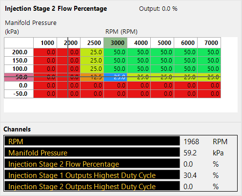
In the above scenario, the ECU is delivering all fuel via Stage 1, as the Stage 2 Flow Percentage is 0%, and Stage 1 has not yet reached its Staging Duty Cycle.
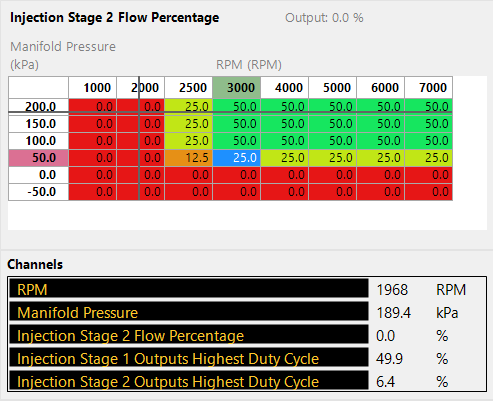
In the above scenario, Stage 1 has reached its Staging Duty Cycle, and Stage 2 is now delivering the additional fuel requirement. Note the output of the Flow Percentage table is still 0%.
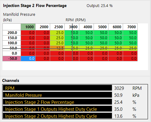
In the above scenario, the Stage 2 Flow Percentage is requesting 25% of the total fuel requirement be delivered to the engine via Stage 2. This reduces the duty cycle of Stage 1.

In the above scenario, the Stage 2 Flow Percentage is now requesting 50% of the total fuel requirement be delivered to the engine via Stage 2. This has further reduced the duty cycle of Stage 1.
In the above scenario, Stage 1 has reached its Staging Duty Cycle, and Stage 2 is now delivering the additional fuel requirement. Note the output of the Flow Percentage table is still 0%.
In the above scenario, the Stage 2 Flow Percentage is requesting 25% of the total fuel requirement be delivered to the engine via Stage 2. This reduces the duty cycle of Stage 1.
In the above scenario, the Stage 2 Flow Percentage is now requesting 50% of the total fuel requirement be delivered to the engine via Stage 2. This has further reduced the duty cycle of Stage 1.
Related Articles
Flow
This table sets the flow rate of the fuel injectors fitted to each injector output in the injection stage. If multiple injectors are fitted per injector output, this is the combined flow rate of all injectors per output. This data is usually supplied ...Fuel Return Flow Sensor
A Fuel Return Flow sensor is used to monitor the amount of fuel flow returning to the tank. It is most commonly combined with a Fuel Flow sensor to exactly calculate the fuel being consumed by the engine by measuring the fuel flow before and after ...Fuel Flow Sensor
A Fuel flow sensor is used to monitor the amount of fuel flowing in the fuel system. It is most commonly combined with a Fuel Return Flow sensor to exactly calculate the fuel being consumed by the engine by measuring the fuel flow before and after ...Mass Air Flow Sensor
The Mass Air Flow (MAF) Sensor provides an input that directly measures the amount of air entering the engine. Up to two MAF Sensors may be used with your ECU. When using a MAF Sensor as the Fuel Load Type, the Tuning Method is typically set to Mass ...Fuel Return Flow Sensor
The Fuel Return Flow sensor is used to monitor the flow of fuel returning from the fuel rail back to the fuel tank. Display warnings will flash in the ESP Software if the flow is to low or too high. Wiring Tab Connections Fuel Return Flow Input ...