Holden V8 5.0L EFI
The fuel injected 5.0L Holden V8 was used in the VN to VT Series 1 Commodore. Early models used a simple mutlipoint injection while the VT received some technical
updates, such as sequential injection via a new distributor, wiring, and ECU.
VN V8 Engine
Important notes when using modified ignition systems with Sport GM ECUs
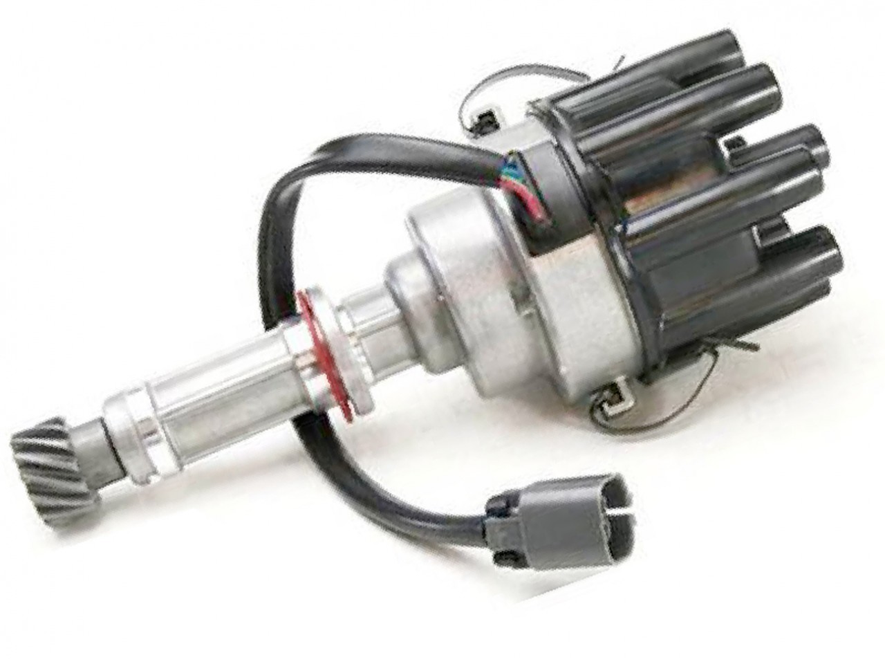
Distributor
A common hack to make wiring simpler is to do the following:
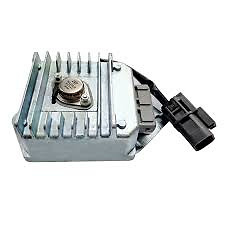
DFI Module
Idle Control
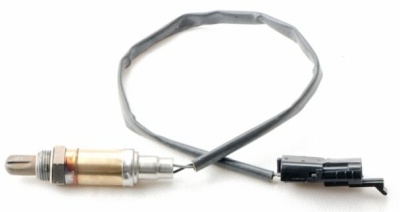
Most narrow band O2 sensors use a black wire for signal. This is often mistaken as the ground wire.
VN-VP
4L80E
Ignition System
| Haltech Elite Series Setting | Value |
Number of Cylinders | 8 |
Capacity | 4987cc (304) or 5737cc (355) |
Firing Order | 1-2-7-8-4-5-6-3 (1357 RHS) |
Engine Type | Piston 4 - Stroke |
Injection Mode | Sequential |
Number of Inj | 8 |
Inj Flow/Size | 220cc |
Inj Current Setting | High |
Ignition Mode | Distributor |
Ignition Edge | Falling |
Ignition Dwell Mode | Constant Charge |
Trigger Tooth Pattern | 8 |
Home Tooth Pattern | 1 |
ESP Trigger Pattern | Holden V8 Commodore VT |
TDC Angle | ~690 (movable distributor) ICE Dizzy ~600 |
Trigger Sensor Type | Hall |
Trigger Sensor Edge | Falling |
Trigger Filter Level | 0 |
Trigger Pullup | Enabled |
Trigger Ground Ref | - |
Home Sensor Type | Hall |
Home Sensor Type | Falling |
Home Filter Level | 0 |
Home Pull-up | Enabled |
Home Ground Ref | - |
Home Min RPM | - |
Quick Start | Disabled |
Notes | When not using OEM BYPASS Module. Home edge occurs 30BTDC Cyl1 which is after the Trigger Edge for Cyl1. This moves the TDC Offset by 7-cylinders (630deg) from 60 to 690. |
Injection System
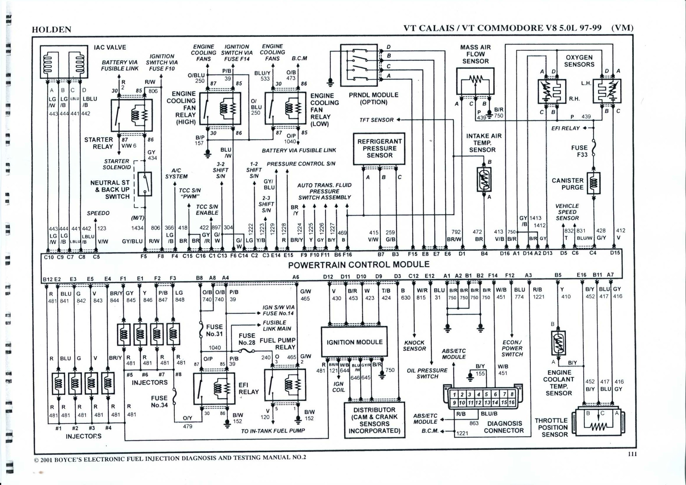
Early VN-VS models used an old style of multipoint injection. In the factory ECU there are only two injector output pins (D15 and D16) and these two are linked together in the wiring. As such there is no other way to fire the injectors other than all of the firing together.
Late VS Series 3 and VT Series 1 models had a change of ECU, distributor, and wiring, together with the addition of a MAF sensor to allow true sequential injection. These have an ECU with 8x injector outputs and a distributor with an 8x and a 1x Hall Effect trigger system. These models have engine covers denoting Sequential Injection.
Recommended Haltech ECU
VN-VS models can use the plug in Platinum Sport GM if the OEM wiring loom is still in place. It is usually advised to move to an Elite 2000 or 2500 for any serious build though. This requires a new wiring loom to be fabricated, however all factory functionality is supported on early models.
VS Series 3 and VT Series 1 require a piggyback style installation if all factory dash functionality is to be retained.
Important notes when using modified ignition systems with Sport GM ECUs
The Platinum Sport GM is designed to run the factory distributor and DFI module. If any of these factory parts have been removed to upgrade, (MSD/ICE Ignitions for example) then custom firmware must be loaded into the Sport GM.
Below are 2 firmware files which will suit most installations.
1.13.1 Experimental 18: Enables pull-up on the trigger. Leaves ignition output as Falling edge.
Used for DFI delete with inductive coil setups (eg. LS1, IGN1A, dumb igniter, ICE ignition)
1.13.1 Experimental 19: Enables pull-up on the trigger. Changes ignition output to Rising edge.
Used for DFI delete with CDI setups (eg. MSD 6AL)
Sensor Information
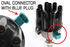
Distributor
VN-VS
This model has markings on the blue connector (+,0,-). For direct connection without a DFI module wire as follows
Distributor Pin | OEM Wire Colour | Haltech Connection |
+ | White/Black | 12V+ (Red) |
| 0 | Light Blue/White | Trigger + (Yellow) |
- | Grey/Red | Signal Ground (Blue) |
VT
For direct connection without a DFI module wire as follows
Distributor Wire Colour | Haltech Connection |
Red | 12V+ (Red) |
Black | Signal Ground (Blue) |
Green | Trigger + (Yellow) |
Blue | Home + (Yellow) |
In the Grey shielded Trigger 4-core cable we have 12V+, Signal Ground, Trigger+, and Trigger-. We need all of these wires except for Trigger -
In the Grey/Black shielded Home 4-core cable we only need the Home+.
If we relocate the Green Trigger- wire so that instead of going to this ECU pin it instead goes to the Home+ ECU pin we now have all of the wires we require in a single 4-core cable.
For Elite 550 / 750 / 950
1. Remove the Yellow wire from ECU pin A32 and insulate it.
2. Remove the Green wire from ECU pin A33 and move it to A32.
For Elite 1000 / 1500 / 2000 / 2500
1. Remove the Yellow wire from ECU pin B2 and insulate it. It will not be used.
2. Remove the Green wire from ECU pin B5 and move it to B2.
DFI Module
VN-VS
VN-VS Factory Connection | VT Factory Connection | Haltech Connection |
B5 Distributor Reference Input (White/Violet) | D12 Reference Signal High (Violet) | Trigger + (Yellow) |
B3 Distributor Reference Earth (Black/Red) | D11 Reference Low (Black/Red) | Signal Ground (Blue) |
D4 EST Output (White) | D10 EST Out (White) | Ignition Output #1 |
D5 Bypass Control | D9 Bypass Control (Teal/Black) | DPO1 (5V Pullup, High State) |
--- | D3 Cam Sensor (Black) | Home + (Yellow) |
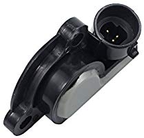
TPS
| Pin | Description |
| A | 5V+ |
| B | Signal Ground |
| C | Signal |
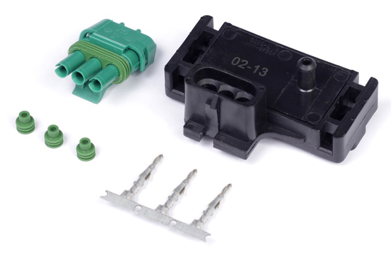
MAP Sensor
The vehicle comes with a 1-Bar MAP sensor, meaning it reads only atmospheric pressure and not any boost pressure.
| Pin | Description |
| A | Signal Ground |
| B | Signal |
| C | 5V+ |
Calibration: Use "MAP - GM 1 Bar.cal"
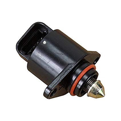
Idle Control
The factory idle control uses a stepper motor. This is only supported on the Sport GM plug in, or the Elite 1000 and higher ECU models.
It is not supported on Elite 550, 750, or 950 ECU models.
| Pin | Haltech Connection |
| A | Stepper 4 |
| B | Stepper 3 |
| C | Stepper 2 |
| D | Stepper 1 |
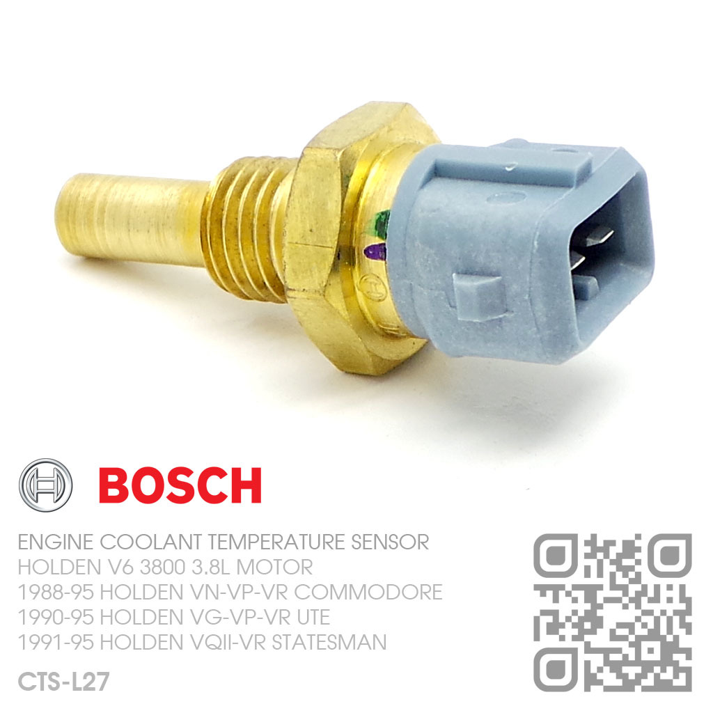
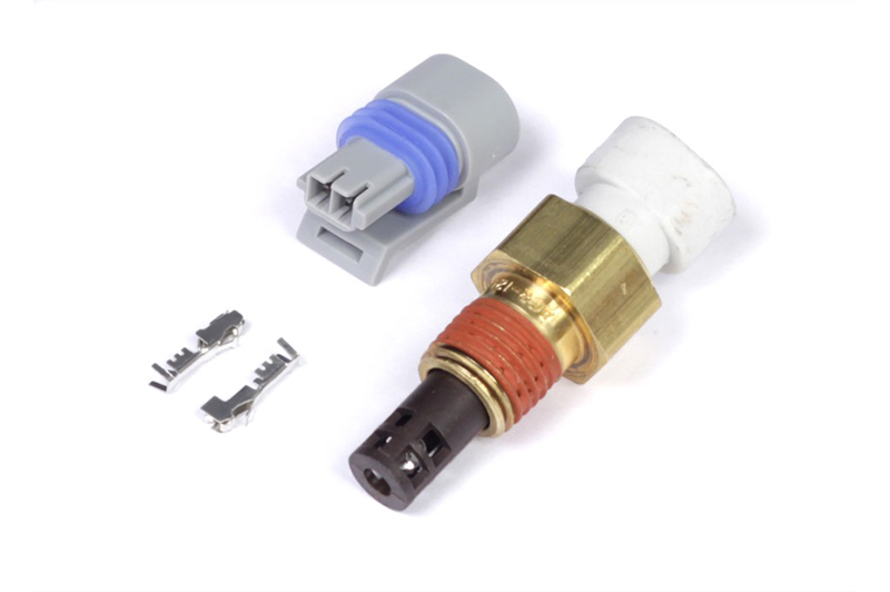
Coolant Temperature
Uses common EV1 connector
Wiring is not polarity sensitive
Calibration: Use "Temperature - Holden VP V8 Coolant Sensor.cal"
Created for Haltech ECUs using a 1k pullup to 5V
Air Temperature
Uses Delphi connector that requires the wire to be fed through the connector first, the pin crimped, and then pull back to lock the pin in place
Wiring is not polarity sensitive.
Calibration: Use "Temperature - Holden VP V8 Air Sensor.cal"
Created for Haltech ECUs using a 1k pullup to 5V
O2 Sensor
Early models used a single narrow band 2-wire O2 sensor located on the LHS exhaust header. There was no need for 2x O2 sensors on these models because the injection was linked anyway so there was no way to do any banked fuel control. These sensors lack a heater and by modern standards are virtually useless. It is strongly recommended to replace the sensor with a wideband O2 kit.
O2 Sensor Wire Colours | Haltech Connection |
Black (Signal) | AVI 1 or AVI 6 |
Grey (Ground) | Sensor Ground |
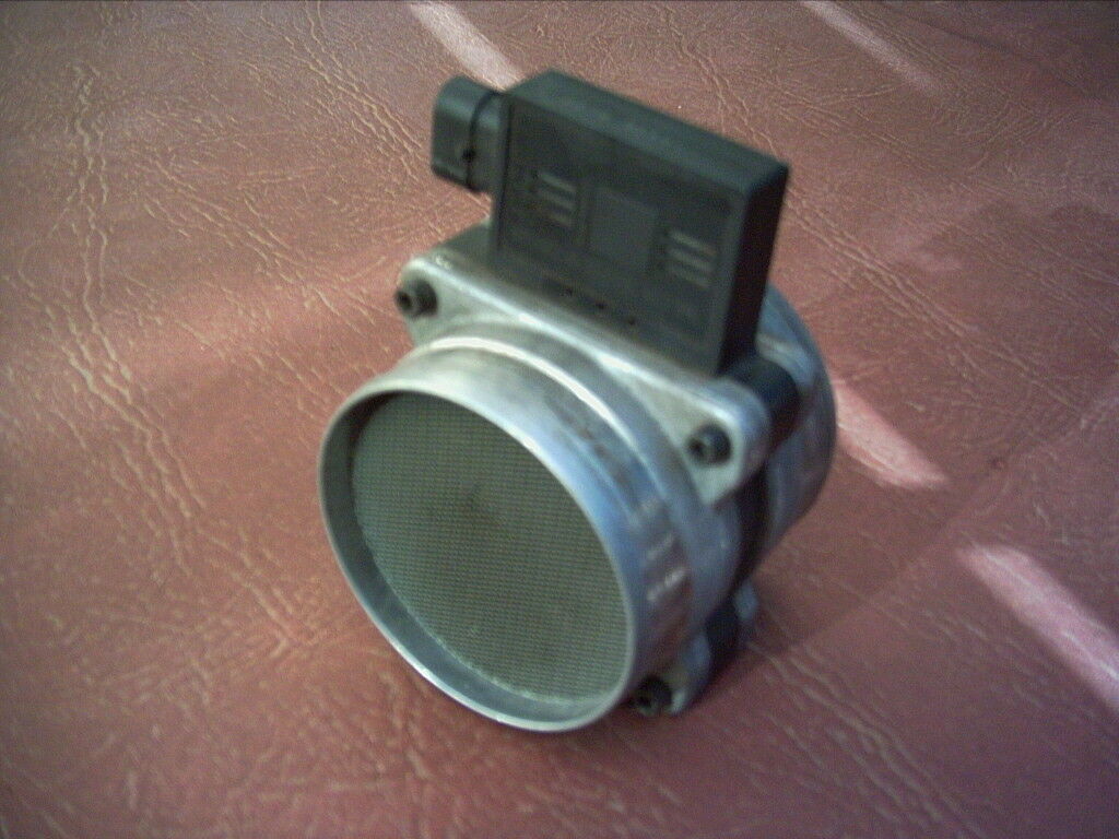
MAF Sensor
The VS Series 3 and VT added a Mass Air Flow (MAF) sensor. This is often deleted when a Haltech ECU is added.
MAF Connection | Haltech Connection |
A - Brown/White (Signal) | Any spare AVI |
B - Black/Red (Ground) | Sensor Ground (Black/White) |
C - Purple (12V+ Switched) | 12V+ Switched (Grey/Red) |
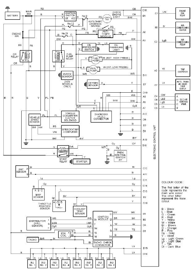
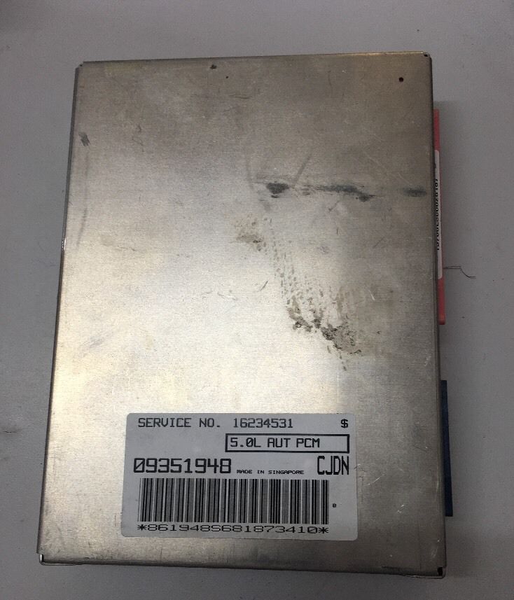
OEM ECU Information
VN-VP
OEM ECU is located in passenger side kick panel
VT
Automatic Transmission
Turbo-Hydramatic 700
The only form of ECU control of the TH700 gearbox is the lock up torque converter connected to OEM ECU pin A7 (grey/red). It is a ground switched output.
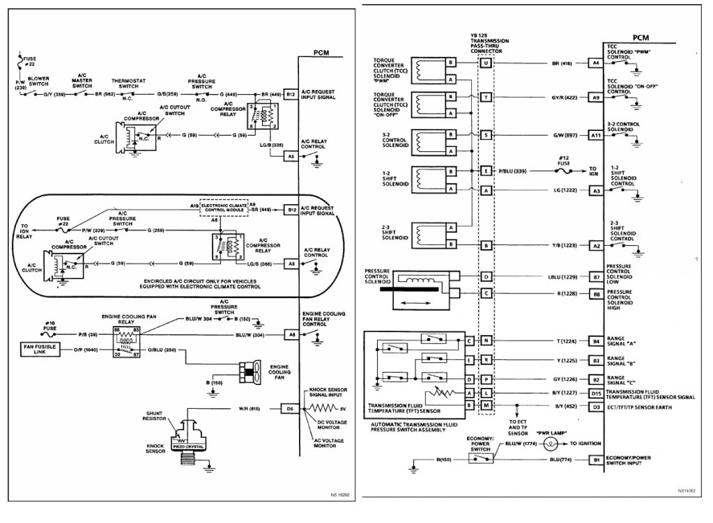
4L80E
The 4L80E transmission requires ECU control of shifting and lock up converter.
Unique Information
Ignition System
These engine use a DFI module ignition system. What makes them unique is that the ignition system will actually still fire a spark to each cylinder without an ECU being present. When an ECU is present it switches to Bypass mode (sends a 5V signal to the Bypass input on the module) where the ECU is then given Distributor signal and will send back a timed signal to the module to fire the spark, thereby controlling ignition timing as every other common ECU ignition system works. The module when not in bypass simply does this by "edge-firing" off the Rising edge of the Distributor signal which is set at 10deg BTDC.
You can actually ensure the distributor is phased correctly by disabling the Bypass signal and physically moving the distributor and checking with a timing light that you have 10BTDC. When set correctly you re-enable the Bypass and check your TDC Offset which is typically around 60deg.
Related Articles
Holden Commodore VE Accelerator Pedal Position (APP)
Overview Accelerator Pedal Position (APP) sensors provide pedal position information to the ECU. This device is used in conjunction with an electronic throttle body and an ECU that supports Drive-By-Wire throttle control (e.g. Elite 1500/2500, Nexus ...Holden/Buick V6 Ecotec
The GM/Holden/Buick ECOTEC V6 engine Haltech ECU Options ECU Model Plug In Available OEM Functions Not Supported Suitable Installation Type Support Sequential and/or Direct Fire Ignition Auto Transmission Control Platinum Sport GM Yes (VN-VP Only) ...GM Alternator Control - VE Commodore
Alternator Control for VE Commodores This alternator is similar to those used on earlier Commodore LS engines but features a PWM-controlled regulator instead. It can be identified by its connector — the earlier unit uses a larger connector compared ...EFI – Power To The People!
Carburetors have been the core of automotive industry as well as its aftermarket, performance and racing segments for over a century. Their successor – the Electronic Fuel Injection (EFI) burst onto the scene in the 1980s and by mid 1990 had become ...1969 Mustang EFI conversion
Engine swapping is not a new idea and fitting modern, fuel injected engines in classic muscle cars is becoming a common practice. This 1969 Ford Mustang owned and built by Emmanuel from Restomod Performance is a perfect example of a well executed EFI ...