How Relays Work and Why You Need One
In this article we are talking relays. Often misunderstood, relays are among some of the most integral components of your car’s electrical system.
A power relay is used when a high current device like a fuel pump or a thermofan needs to be triggered from a low current output like an ECU or a dash-mounted switch.

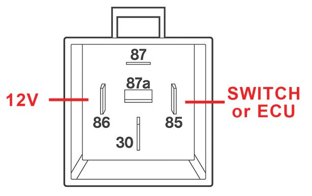
Power relays are available in a huge range of configurations for an even bigger range of applications, for this article we will concentrate on a simple 4 pin relay.
As the name suggests the relay has 4 pins. Inside the relay we will find two circuits – one for low and one for high current. The low current circuit’s job is to switch the high current load on while drawing the least amount of current possible.
To do this 2 pins are needed:
PIN 86: This should be connected to a 12V supply which turns off when the cars ignition is turned off and normally draws only around half an Amp of current.
PIN 85: This should be connected to the ECU or a dashboard switch and should pull to ground when switched or activated.
Note that we are switching the ground on and off to trigger the relay? This is most common in the automotive industry but you can also supply constant ground to Pin 85 and have the switch supply power to Pin 86 if that is how your wiring is already done.

Now to the high current side.
PIN 30: This should be connected to the battery through a fuse and should be capable of supplying whatever current the load (the fan or pump) requires. This could be 10, 20 or more than 30 Amps depending on the device. Make sure to use the correct gauge/thickness of wire and correct fuse size.
PIN 87: This is the supply output to the device, ie the power supply to the fan or pump. Your wiring will need to support the same current as Pin 30.
The device will then be grounded to the chassis and again, you will need the right wire gauge to support the high current load.

How does it all work?
Pin 85 and 86 are connected to a coil of wire which is wound around a little iron core. When you apply power to a coil like this it makes a little electromagnetic field.
When that electromagnetic field is present an “Armature” capable of carrying high current connects Pin 30 and 87. When the electromagnetic field is de-energised the armature naturally opens causing the circuit to open and consequently the device to turn off.

So there you have it. If you need to activate a heavy load, high current device using a small, light load switch – you will need a Power Relay!
Related Articles
Engine Control Relay
Engine Control Relay The Engine Control Relay function allows the Nexus ECU to control the 12V+ power supply to certain parts of the engine management, such as injectors and ignition coils. This function should remain enabled when a Haltech supplied ...Engine Control Relay ( ECR )
The engine control relay is the main relay that is used to enable and disable power to the engine management components. The Elite 2500 has one dedicated engine control relay output (DPO 6 (Black/Red)) capable of sinking 1A Max current ( ie 5 x 80 ...Power Steering Pressure Switch
The Power Steering Switch is used to determine when power steering is actively loading the engine. This allows a signal to be sent to the ECU so that it can compensate for this when the system exceeds power steering load limits - such as by ...Power and Ground Wiring
Black (Battery Ground) Red_Green / Red / Red_White (Battery Supply 12V) Pink (Ignition Switch 12V) Locate and connect the following flying leads.(Wiring based on the Haltech Elite Premium Harnesses)Idle Control Wiring
This article explains the most common types of idle air control valves and how to wire them up using a Haltech Nexus or Elite ECU: Bypass Air Control (BAC) Two Wire This type of idle valve is the simplest to wire up, being a solenoid with just two ...