LT1 350 Gen II Engine
Information on the Chevrolet LT1 350 Gen2 engine
Haltech ECU Options
All models can use the Elite 950 but will lose the Idle Control
All models can use the Elite 2000 or 2500 with full control.
General Information
| Cylinders | 8 |
| Displacement | 5733 cc / 349.8 ci |
| Firing Order | 1,8,4,3,6,5,7,2 |
| Cylinder Orientation | Looking at the engine from the front 1357 RHS 2468 LHS |
Model Variants
There are a number of variants of the LT1 engine.
1992-1993
10.4:1 compression ratio, 5700rpm limit, Optispark ignition, MAP sensor, 2x injector outputs with Batch Fire, some models alloy head some cast iron, some are 2 bolt some are 4 bolt mains
1994-95
MAF Sensor replaces MAP, Sequential injection, vacuum vents for optispark distributor
1996-1997
Rear O2 sensors and extra catalytic converter for some models, OBD-2 capable,
Sensor Information
Distributor
An optical Hall Effect trigger is used. This is located inside a distributor called an Optispark that is located on the front of the engine below the water pump.
The sensor unit has 2x optical pickups and works in an indentical way to the very common Nissan Optical systems. The disc has 360x slots around the outside for one pick, with the inner pickup having 8x slots. 4x are small and the same size, another alterate 4x hve different slot sizes and this is what tells the ECu which cylinder is firing. This is supported by the Haltech Elite ECU.
Optispark Distributor Wiring
| Pin | Description | Haltech Connection |
| A | 8x Lo Res | Trigger input |
| B | 360x Hi Res | Home input |
| C | 12V+ Ignition Switch | Any switched 12v source |
| D | Signal Ground | Signal ground |
Ignition Coil and Igniter
The ignition coil on this engine uses an external igniter module. OEM diagram is shown above in the Distributor Wiring section.
| Pin | Description | Haltech Connection |
| A | Coil - | --- |
| B | Ignition Control | Ignition Output 1 Yellow/Black |
| C | Ground to Cylinder Head | --- |
D | 12V+ Ignition Switch | --- |
Dwell Time
Throttle Position Sensor
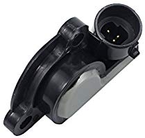
Pin
Description
A
5V+
B
Signal Ground
C
Signal
| Pin | Description |
| A | 5V+ |
| B | Signal Ground |
| C | Signal |
MAP Sensor
The LT1 comes with a 1-Bar MAP sensor, meaning it reads only atmospheric pressure and not any boost pressure.
| Pin | Description |
| A | Signal Ground |
| B | Signal |
| C | 5V+ |
Calibration: Use "MAP - GM 1 Bar.cal"
Idle Valve
This engine uses a Stepper Motor idle valve controlled via the Stepper Outputs. It will not work on Elite 550/750/950 ECU models, but will work on Elite 1000/1500/2000/2500 models.
4-pin Stepper Motor Wiring
| Pin | Haltech Connection |
| A | Stepper 4 |
| B | Stepper 3 |
| C | Stepper 2 |
| D | Stepper 1 |
Drive Type: Both Steps:240 Speed:75
Coolant Temperature
Uses common EV1 connector
Wiring is not polarity sensitive
Calibration: Use "Temperature - Holden VP V8 Coolant Sensor.cal"
Created for Haltech ECUs using a 1k pullup to 5V
Air Temperature
Uses Delphi connector that requires the wire to be fed through the connector first, the pin crimped, and then pull back to lock the pin in place
Wiring is not polarity sensitive.
Calibration: Use "Temperature - Holden VP V8 Air Sensor.cal"
Created for Haltech ECUs using a 1k pullup to 5V
MAF Sensor
Although most users of Haltech ECUs will be deleting the MAF, it is possible to use a MAF if you prefer.
| Pin | Description | Haltech Connetion |
| A | Signal | Spare AVI |
| B | Signal Ground | Signal Ground (black/white) |
| C | 12V+ Swtiched | --- (grey/red) |
O2 Sensors
The LT1 comes with narrow band O2 sensors. Although they can be used for light load and low RPM use, they are not useful for engine tuning. The Haltech WB2 kit should be used.
Adding a Haltech 2-channel Wideband WB2 Kit (highly recommended)
For correct operation a Haltech WB2 kit is highly recommended for this application, with the provided 4.9 sensors replacing the pre-cat sensors. Sensors use a 22mm socket or spanner to remove and replace.
Vehicle Speed Sensor
This engine uses a Reluctor Vehicle Speed sensor.
Reluctor Speed Sensor Wiring
| Pin | Description | Haltech Connection |
| A | VSS Low Signal | Signal Ground |
| B | VSS High Signal | Spare SPI |
Injector Data
All models, incluing the early batch fire models of the LT1, support sequential injection.
Flow
The injector flow rate is measured with the injectors held wide open at 100% duty. For fuel systems with a fixed regulator pressure (often returnless systems) that is not referenced to manifold pressure the flow needs to be mapped over Manifold Pressure for accurate tuning.
Injector Flow: 260 cc/min (24.9 lbs/hr)
Dead Time
When an injector is commanded to open for a certain amount of time, the dead time is the amount of time the injector is not actually open during this period. It covers the time to energise the solenoid and begin to open and the time to close as well. There are also transient periods during which the injector is opening and closing where fuel flow is not at full capacity so this lost peak flow period is also taken into account.
Automatic Transmission
The LT1 came with the option of a 4L60E automatic transmission. Supported is to be added to the Elite ECU range shortly.
OEM ECU Information
Location
The ECU is located in the engine bay near the windscreen on the drivers side.