RB20/25/26 Engine
The RB series of engines are among the most popular and desirable engines in today's enthusiast society. There is no other engine that sounds quite like a twin cam RB. They are known for a power-band that is smooth and increases as it progresses throughout the rpm range. Because of this, the RB engine can be one of the most exciting power-plants to pilot, that came out of Japan in the 90's.

Model Variants
RB20DE
RB20DET
RB25DE
RB25DET
RB25DE NEO
RB25DET NEO
RB26DETT (R32/R33)
RB26DETT (R34)
RB30E
RB30ET
Injection System
Recommended Haltech ECU
Sensor Information
CAS Crank Angle Sensor
Igniter and Coils
Igniter
Coils
Dwell
TPS
MAP Sensor
Variable Cam (N-VTC)
Idle Control

Coolant Temperature
Air Temperature
O2 Sensor
Boost Control System
MAF Sensor
OEM ECU Information
In all R32/33/34's the OEM ECU is located in passenger side kick panel

| Haltech Elite Series Setting | Value |
Number of Cylinders | 6 |
Capacity | 2.0, 2.5, 2.6 Liters |
Firing Order | 1-5-3-6-2-4 |
Engine Type | Piston 4 - Stroke |
Injection Mode | Sequential |
Number of Inj | 6 |
Inj Flow/Size | 240cc, 370cc, 440cc |
Inj Current Setting | High Low with Resistor Box removed for the RB26 |
Ignition Mode | Direct Fire |
Ignition Edge | Falling |
Ignition Dwell Mode | Constant Charge |
Trigger Tooth Pattern | 6 Evenly spaced windows, All window sizes are unique, Rising edge locked |
Home Tooth Pattern | 360 Evenly spaced windows, Rising edge locked |
ESP Trigger Pattern | Nissan RB20, RB25, RB26 |
TDC Angle | 109 is the base but, it does have an adjustable CAS so verifying this number is a necessity. |
Trigger Sensor Type | Hall |
Trigger Sensor Edge | Rising (locked) |
Trigger Filter Level | 0 |
Trigger Pullup | Strong yields the best results. |
Trigger Ground Ref | - |
Home Sensor Type | Hall |
Home Sensor Type | Rising (locked) |
Home Filter Level | 0 |
Home Pull-up | Strong yields the best results. |
Home Ground Ref | - |
Home Min RPM | - |
Quick Start | Disabled (pattern does not support) |
Notes |
Model Variants
RB20DE
1998cc, aspirated, DOHC 24V head, 10.0:1 comp
RB20DET
1998cc, turbo, DOHC 24V head, 8.5:1 comp
RB25DE
2498cc, aspirated, DOHC 24V head, 10.0:1 comp
RB25DET
2498cc, turbo, DOHC 24V head, 8.5:1 comp, N-VTC.
RB25DE NEO
2498cc, aspirated, DOHC 24V head, 10.0:1 comp, N-VTC.
RB25DET NEO
2498cc, turbo, DOHC 24V head, 9.0:1 comp, different turbo from conventional RB25DET, N-VTC
RB26DETT (R32/R33)
2568cc, turbo, DOHC 24V head, 6x throttle ITB intake, Twin Turbos
RB26DETT (R34)
2568cc, turbo, DOHC 24V head, 8.5:1 comp, 6x throttle ITB intake, Twin Turbos, red valve covers
RB30E
2962cc, aspirated, SOHC 12V head, 9.0:1 comp, distributor ignition
RB30ET
2962cc, turbo, SOHC 12V head, 7.8:1 comp, distributor ignition, no intercooler
Injection System
RB twin cam engines all share the same basic sequential fuel injection strategy.
Some models have a ballast resistor pack that should be bypassed if the injectors are to be changed.
Recommended Haltech ECU
The R32/33 platinum pro plugin found here: https://www.haltech.com/product/ht-055101-platinum-pro-plug-in-ecu/ is a very popular unit for mildly modified engines using oem harnesses and sensors. I always suggest the Elite 2000/2500 pnp kits found here: https://www.haltech.com/product/ht-151257-elite-2000-nissan-skyline-r32-r33-r34-gt-r/ and here: https://www.haltech.com/product/ht-151357-elite-2500-nissan-skyline-r32-33-r34-gt-r/ for those with heavily modified engines and aftermarket crank and cam triggers/sensors. If on a budget, the Elite 750 and a custom premium wiring harness found here:https://www.haltech.com/product/ht-150604-elite-750/ or plug and pin kit found here: https://www.haltech.com/product/ht-030009-plug-and-pins-only-amp-34-pin-4-row/, can be very capable. You will just be limited on inputs/outputs to the most basic functions.
Sensor Information
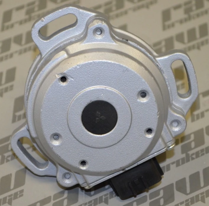
CAS Crank Angle Sensor
The DOHC RB models all have a cam angle sensor located on the front of the engine driven by the exhaust cam. One major issue with this is that the drive belt and camshaft vibrate at high RPM, with higher lift camshafts performing much worse. The solution for all high power RB engines is to use a crank trigger kit, of which there are many suppliers. Virtually all crank trigger kits are supported by the Elite ECU, with only a 12x crank tooth pattern being supported on the Platinum Pro range. It is preferred to use a missing-tooth style pattern if it is available from the manufacturer when an Elite ECU is used, and either Hall or Reluctor can be used.
OEM Sensor
R32/33 Sensor shown below:
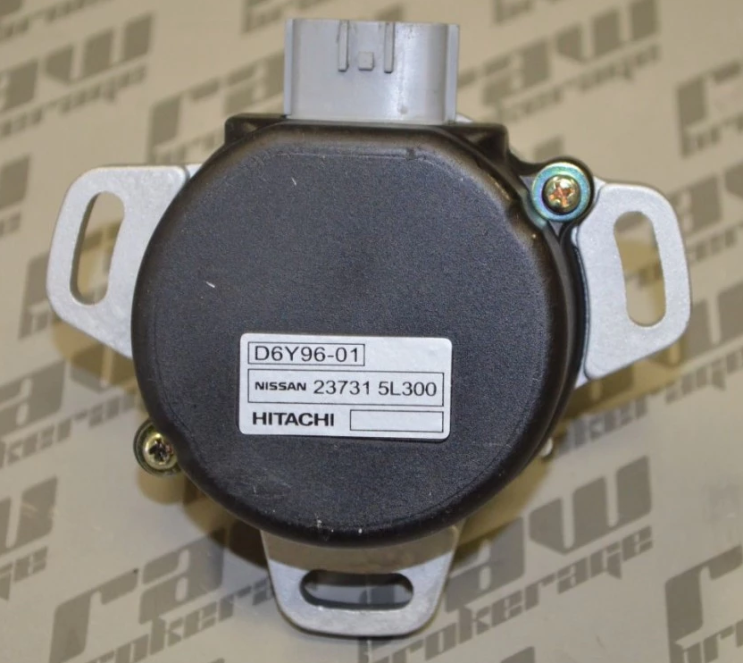
R34 Sensor shown below:
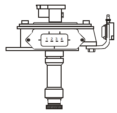
Nissan CAS or crank angle sensor is a crankshaft position sensor driven from the exhaust cam. The CAS, sometimes called a cam angle sensor by mistake, has an optical wheel inside that is driven at 1/2 of the crank speed. It has two sets of slots inside. One set is 360 one for each degree. The other set is 6, or one for every 120 degrees of crank rotation. The signals are typically labeled as the 1 and 120 signals.
It uses a single external coil and a single channel igniter module.
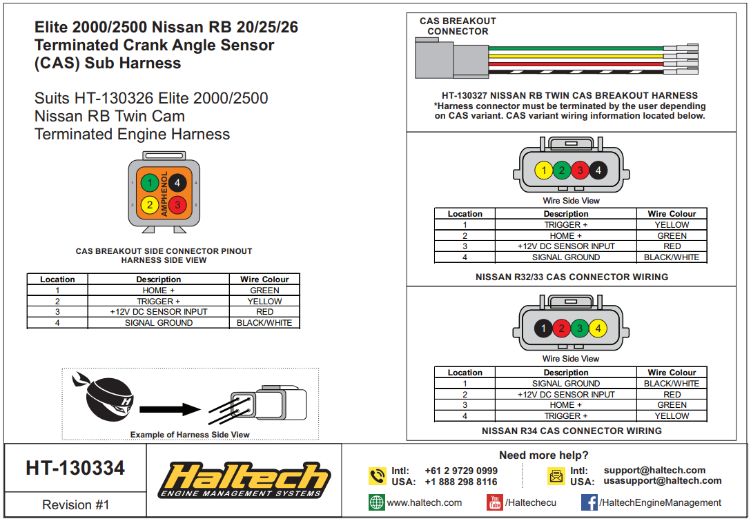
Pin | Function | Haltech Connection |
1 | Ground | Signal Ground in Trigger 4-core (blue) |
2 | Power | 12V+ in Trigger 4-core (red) |
3 | 360x | Home + in Home 4-core (yellow) |
4 | 6x | Trigger + in Trigger 4-core (yellow) |
Igniter and Coils
Early models have an external 6-channel igniter module located on the rear section of the coil cover. There were various ignition coil types used.
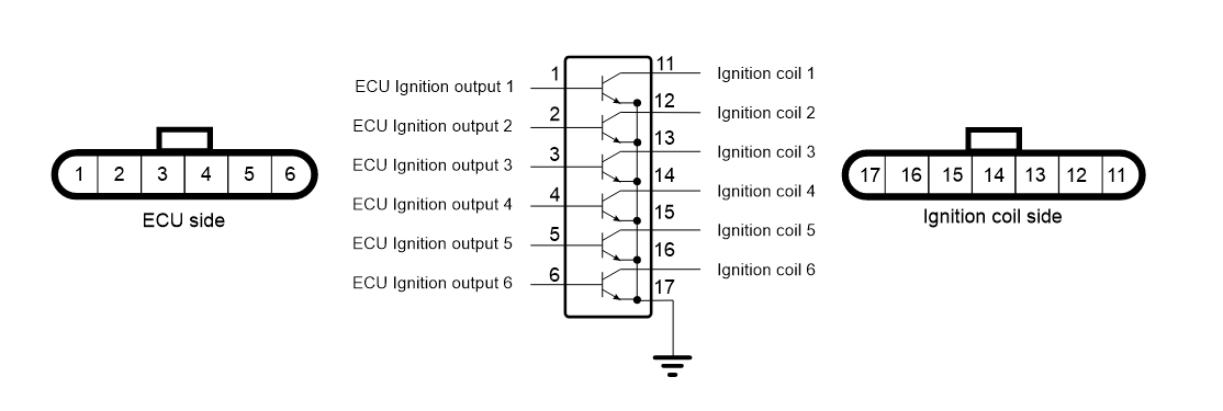
Igniter
For models that have an external igniter, the wiring for them is labelled on the igniter itself
Pin | Function |
1 | ECU Ignition 1 |
2 | ECU Ignition 2 |
3 | ECU Ignition 3 |
| 4 | ECU Ignition 4 |
5 | ECU Ignition 5 |
6 | ECU Ignition 6 |
11 | Ignition coil signal 1 |
12 | Ignition coil signal 2 |
13 | Ignition coil signal 3 |
14 | Ignition coil signal 4 |
15 | Ignition coil signal 5 |
16 | Ignition coil signal 6 |
17 | Engine ground |
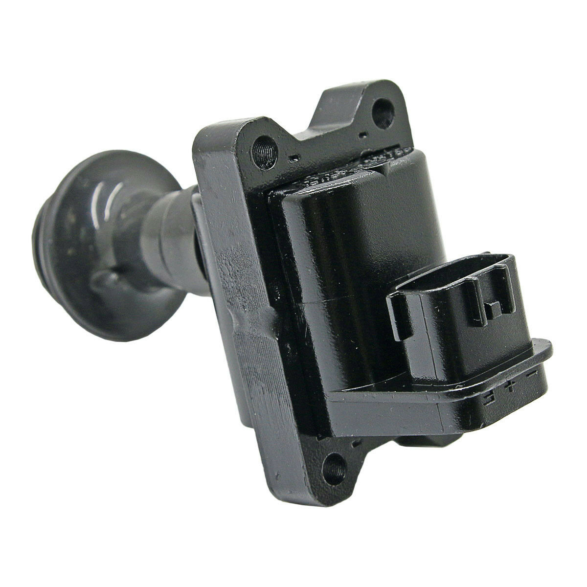
Coils
Wiring details are labelled on the coil
Early Coils (RB25 Series 1 and older) use an external igniter. They CANNOT be wired directly to the ECU.
| Pin | Description |
| - | Igniter Module Signal |
| + | 12V+ Switched |
| E | Ground (to head) |
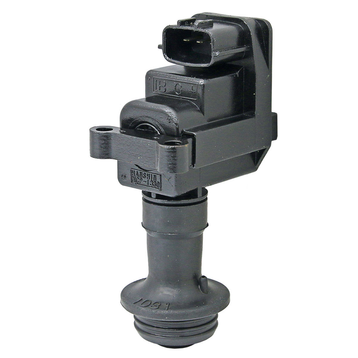
Later Coils (RB25 Series 2 and newer) have an internal igniter and can be directly wired to the ECU.
| Pin | Description |
| IB | ECU Ignition Output |
| G | Ground (to head) |
| + | 12V+ Switched |
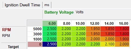
Dwell
Suggested dwell time for Nissan Coils
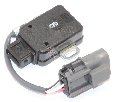
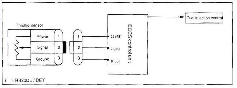
TPS
The cable connection is used for Haltech ECUs, and NOT the connection directly on the sensor.
MAP Sensor
The RB series of engines do not come with a factory map sensor. They are typically fitted with a MAF sensor for airflow monitoring. With that said, we typically use the onboard map sensor or one of our many external map sensor options found here: https://www.haltech.com/product-category/ecu-inputs-and-o2-wideband-controllers/map-sensors/
Some models have a MAP sensor present but this is only used for the boost gauge on the dash and is not connected to the ECU.
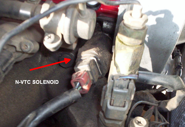
Variable Cam (N-VTC)
The RB25DET motors have the N-VTC (Nissan Variable Timing Control). This is a switched variable intake cam control system and is supported by all Haltech ECU models with the control solenoid located near the fuel pressure regulator.
Wiring involves connecting a switched 12V+ power source, and connect any spare ECU output (except ignition outputs) directly to the solenoid.
Idle Control
The factory idle control uses a simple 2 wire idle control motor. Any of our ecus can control a 2 wire type idle motor.
Most variants have 2x idle solenoids. The larger solenoid is the normal idle control valve. The smaller solenoid is a switched on/off type that is not wired to the ECU. It instead is switched on anytime the A/C Compressor is active.
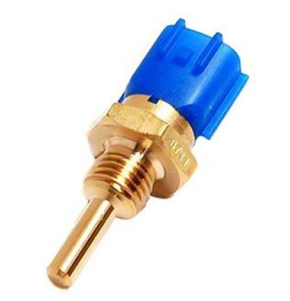
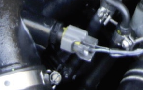
Coolant Temperature
Wiring is not polarity sensitive
Calibration: Use Temperature - Nissan Skyline R32 R33 R34 Coolant Sensor.cal
Air Temperature
RB26DETT Air Temp Sensor in stock location.
The RB26DETT engine does have an air temp sensor threaded into the intake manifold near the front. This sensor is known to have a very slow response rate and prone to heat soak due to its location. For that reason, we suggest replacing this sensor with one of our air temp sensors found here: https://www.haltech.com/product-category/ecu-inputs-and-o2-wideband-controllers/air-temp-sensors/
These sensors should be installed in front of the throttle body in the intercooler piping. Wiring is not polarity sensitive.
Other RB variants do not come with an Air Temperature Sensor, and these models should have the sensor added when using a Haltech ECU. The ideal location is in the intake plenum, however it can be added to an intercooler pipe near to the throttle body.
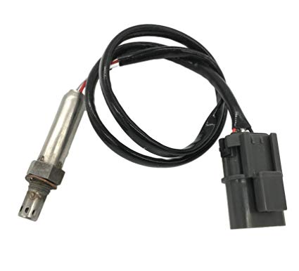
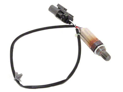
O2 Sensor
Most RB variants have a single O2 sensor located on the down-pipe after the turbo. Twin turbo models (RB26DETT) have 2x O2 sensors, one for each turbo down-pipe.
Older style O2 sensors are of a Titania type. These actually vary resistance to the ECU but they can still be used. They typically have an offset voltage output reading from around 0.4V to 1.4V, so a crossing voltage of around 0.7 to 0.8V will work better.
Newer style O2 sensors are of a Zirconia type and these are the same as all common 0-1V sensors used throughout the auto industry.
These sensors only have a 1v sweep and by modern standards are not suitable for engine tuning. It is strongly recommended to replace the sensor with a wideband O2 kit found here: https://www.haltech.com/product/ht-159976-wb1-single-channel-can-o2-wideband-controller-kit/.
Boost Control System
RB engines have a boost control solenoid. The solenoid however is plumbed in such as way as to only offer a small amount of boost increase. Instead of the valve acting as the distribution point, it is instead located on the section of the venting hose that comes off the T-piece, which restricts the amount of pressure that can be vented. The OEM vent hose also has a restrictor pill inside the hose and this can be located where the hose has a paint stripe. As such the valve is only of a 2-port style and cannot be re-plumbed to give better control.
When boost control is to be handled by the Haltech ECU all of the plumbing should be redone to suit the Haltech Boost Control Solenoid. The OEM wiring can be used to control the new solenoid.
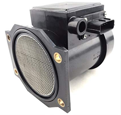
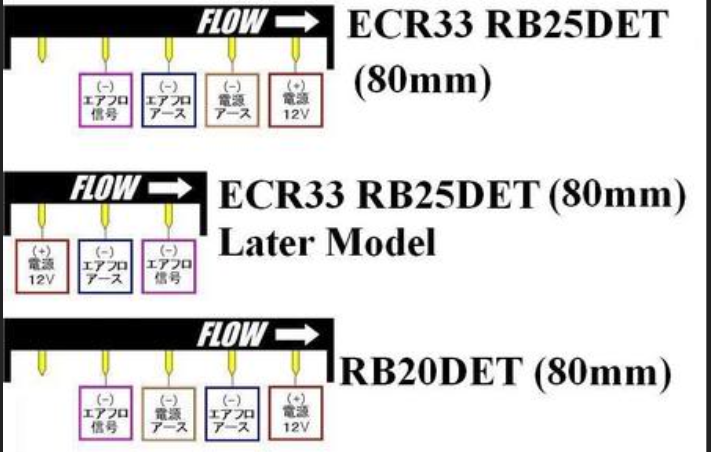
MAF Sensor
All of the twin cam RB's used a Mass Air Flow (MAF) sensor with the RB26DETT having 2x MAF Sensors. This is often deleted when a Haltech ECU is added however it is possible to use them if this is preferred by the tuner.
This is the Color Code for the following diagram.
Red: 12v Switched Power
Purple: Signal
Blue: Ground
Brown: Ground to Chassis
ATTESA 4WD System
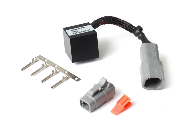
ATTESA (Advanced Total Traction Engineering System for All-Terrain) is Nissan's control system that allows an All Wheel Drive vehicle to normally have drive to just the rear wheels, and as conditions require power can be directed to the front wheels. The ATTESA system has it's own ECU to handle this, but does require a Throttle Position reading. This is provided normally from the OEM ECU as a 0-5V signal with ~0.5V for 0% TPS and ~4.0V for 100% TPS.
All plug in ECUs and adapter harness kits from Haltech incorporate hardware that allows this signal output to occur, and this is mappable as a 0-100% duty signal.
For vehicles that are wired directly Haltech offers a TPS Output device to support the ATTESA system. Part No. HT-038001
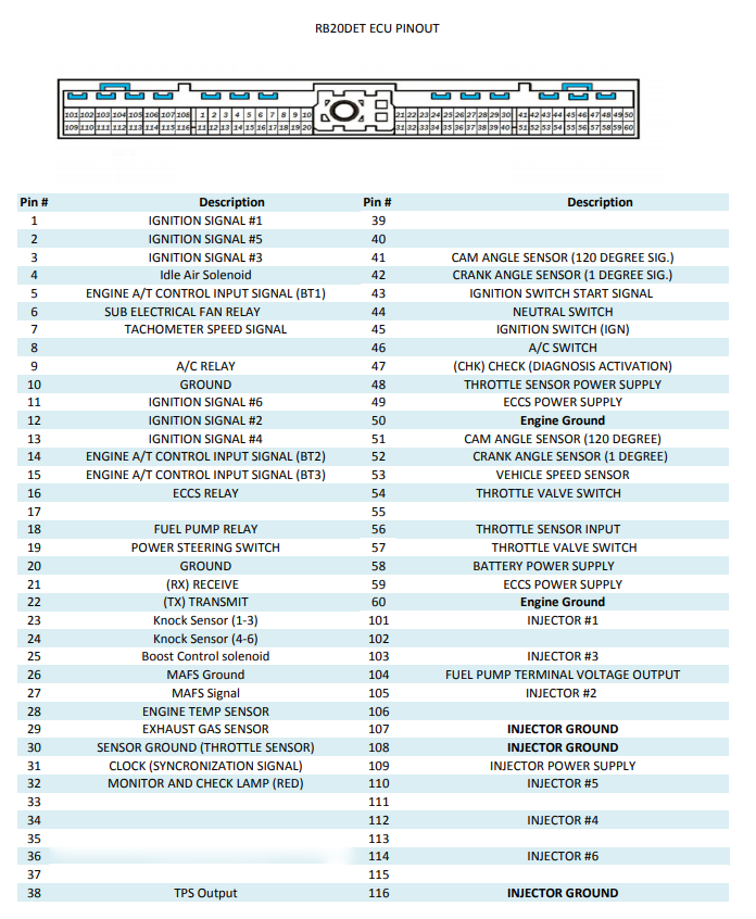
OEM ECU Information
In all R32/33/34's the OEM ECU is located in passenger side kick panel
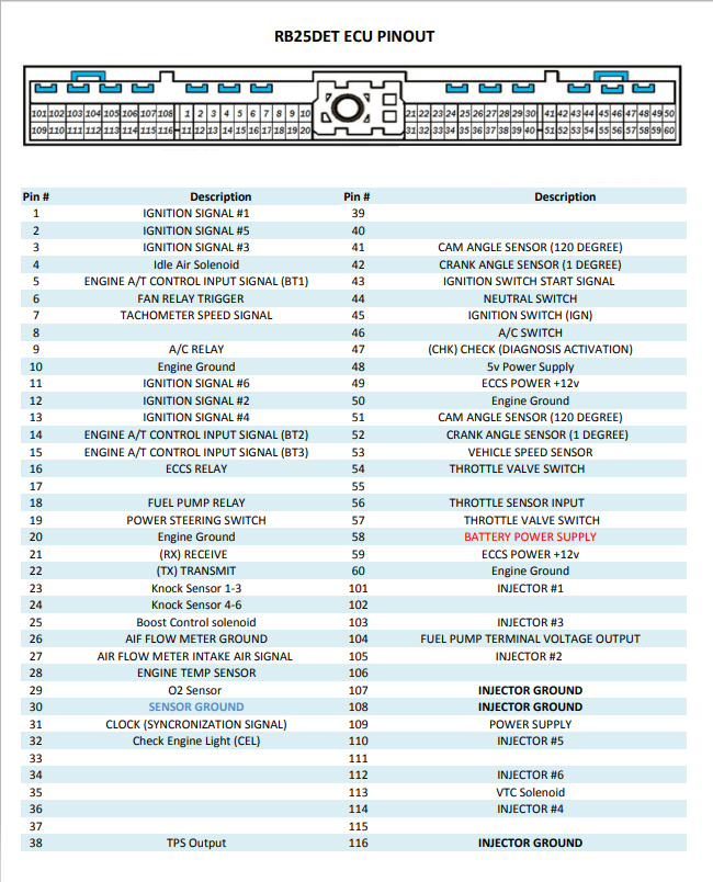
R32 RB25DE / RB20DET ECU Pinout
R33 RB25DET ECU Pinout
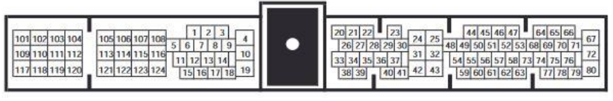
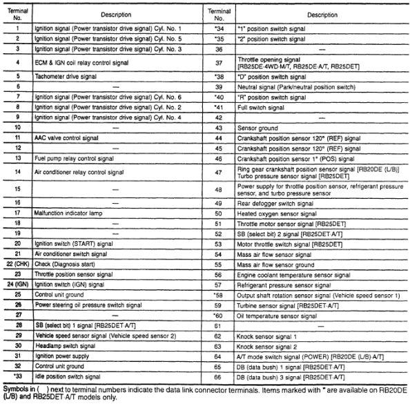
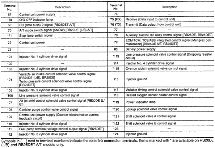
R34 RB25DET NEO (GTT) ECU Pinout
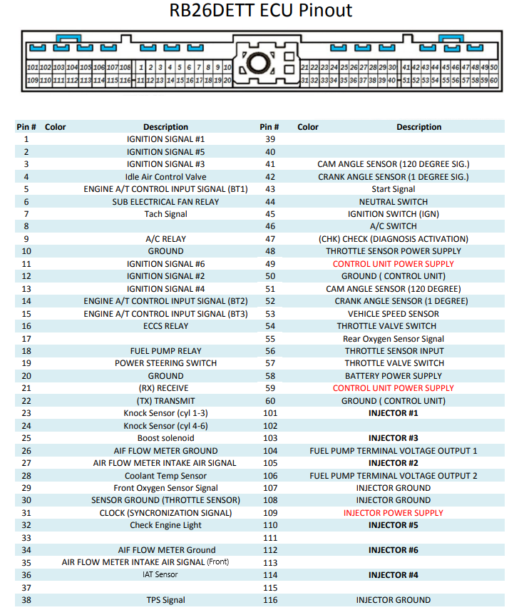
R32/33/34 RB26DETT ECU Pinout
Related Articles
Nissan CAS – Facts and Fiction
The Hot Debate One of the most hotly debated topics within the global RB community is the accuracy of the Nissan OEM Cam Angle Sensor (CAS). In this article we will attempt to separate facts from fallacies, explain the cause of the problem and ...Nexus R3 Terminated Harness for Nissan RB
Nexus R3 Terminated Harness for Nissan RB Overview Congratulations on purchasing a Nissan RB terminated wiring harness for a Nexus R3 VCU! This specialized harness is designed for engine conversions using the following Nissan RB engines: RB20DET ...Trigger Wiring (Crank and Cam Angle Sensors)
The most critical sensor on the engine is the engine speed sensor, without this sensor the ECU would not know that the engine is moving and therefore it would never fire a spark nor inject any fuel. The ECU gets information from the crankshaft and ...Trigger System
Engine Configuration - Trigger System Page This section contains setup information for configuring your engines' trigger system, including crank and cam trigger patterns and sensors. Select Trigger System This button allows automatic selection of ...Engine Trigger Systems Explained
The most important sensors on your engine are the Crankshaft and Camshaft Position Sensors. These sensors have to be wired and configured correctly in order for the engine to start, let alone run well. We refer to the crankshaft position ...