Injection Staging
This node contains settings and tables for the injection stage. There is a separate node for each stage of injection.
Setup - this sets the injector current control mode for each injector output on this stage. This setting must be set correctly for the accurate operation of the fuel injection system. Whenever there is more than 1 fuel injector per output, this should be set to 'Custom' and appropriate values entered. For impedance information on your fuel injectors, see the supplier/manufacturer documentation.
1 - 3 Ohm - Current Controlled 4000mA Peak. 1000mA Hold.
3 - 8 Ohm - Current Controlled 2000mA Peak. 500mA Hold.
3 - 8 Ohm - Current Controlled 2000mA Peak. 500mA Hold.
High - Saturated. No current control. (most common)
Custom - see below
Custom Settings - only used when 'Setup' is 'Custom'. This mode should only be used when you have specific data supplied by the injector manufacturer
Peak Current - this is the current supplied to the injector to initially open it.
Peak Hold Time - the peak current will be supplied to the injector for this amount of time, unless the calculated effective injection time is less, in which case the event will be cut short. The hold time starts once the injection output reaches the peak current value.
Hold Current - this is the current supplied to the injector for the remaining duration of the injection event after the peak hold time.
Staged Injection
With Nexus staging, each injection stage will operate up until it reaches its 'Staging Duty Cycle', at which point that stage will hold its duty cycle and the next injection stage will start to deliver fuel. This repeats for each injection stage that reaches its 'Staging Duty Cycle'. Once all injection stages have reached their 'Staging Duty Cycle', all stages will increase their duty cycle to 100% together. The rate of increase of each stage is controlled so all stages reach 100% duty cycle at the same time.
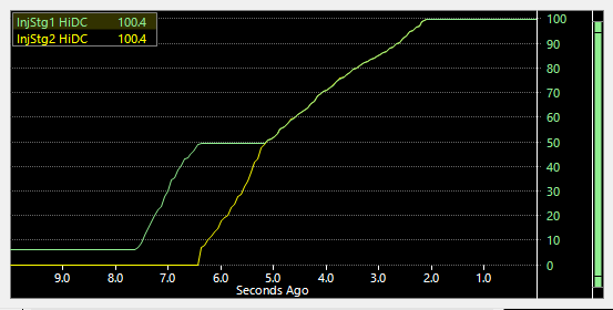
Example: 2 stages of injection with Stage 1 Staging Duty Cycle set to 50%, and Stage 2 Staging Duty Cycle set to 50%.
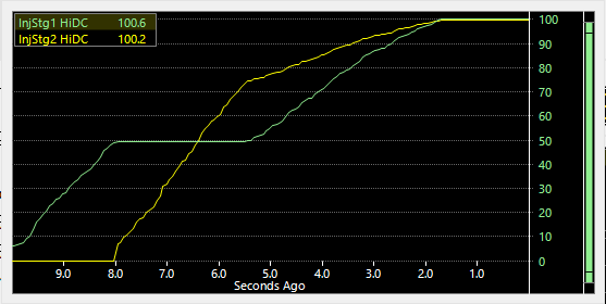
Example: 2 stages of injection with Stage 1 Staging Duty Cycle set to 50%, and Stage 2 Staging Duty Cycle set to 75%.
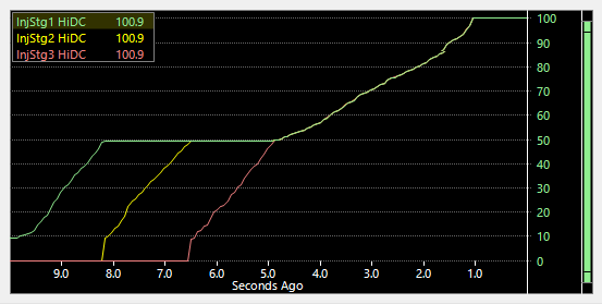
Example: 3 stages of injection with Stage 1 Staging Duty Cycle set to 50%, Stage 2 Staging Duty Cycle set to 50% and Stage 3 Staging Duty Cycle set to 50%.
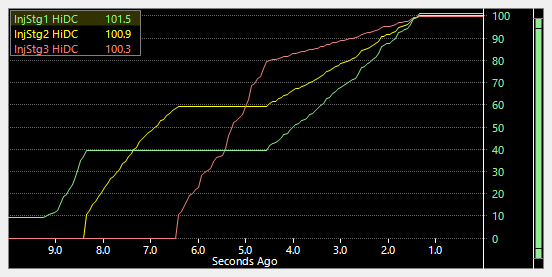
Example: 3 stages of injection with Stage 1 Staging Duty Cycle set to 40%, Stage 2 Staging Duty Cycle set to 60% and Stage 3 Staging Duty Cycle set to 80%.
Example: 3 stages of injection with Stage 1 Staging Duty Cycle set to 50%, Stage 2 Staging Duty Cycle set to 50% and Stage 3 Staging Duty Cycle set to 50%.
Example: 3 stages of injection with Stage 1 Staging Duty Cycle set to 40%, Stage 2 Staging Duty Cycle set to 60% and Stage 3 Staging Duty Cycle set to 80%.
Related Articles
Fuel
This section contains setup information for fuel configuration, including number of stages, injection mode, tuning method, and table selection. Page Contents Fuel Tuning Method Volumetric Efficiency Mass Air Flow Injection Time Auto V.E. Air Temp ...Fuel System
Fuel System This page is used to configure the Fuel Injection System. Injection System Disable Injectors Enabling this will disable all injector outputs. (Default = Disabled) Enable Short Pulse Width Adder Enabling this will add a Short Pulse Width ...Base - Stage 2
The Base - Stage 2 table exists only when the fuel Tuning Method is set to Injection Time and it serves as the raw injection time as delivered through the stage 2 injection system.Flow
This table sets the flow rate of the fuel injectors fitted to each injector output in the injection stage. If multiple injectors are fitted per injector output, this is the combined flow rate of all injectors per output. This data is usually supplied ...Staging Indicator
This function uses an output to indicate when the engine is in the staging section of map, i.e When the load has increased beyond the Staging Load Bar in the Fuel Setup page.There are no parameters to setup for this output. This output will not ...