Throttle Position Sensor - Finding the Correct Wiring
This guide is to help find the correct wiring of a Throttle Position Sensor (here in referred to as a TPS) when the information is not provided by the manufacturer.
What is a TPS?
A TPS provides throttle opening angle information the engine management system. This is used for many aspects of engine control from use as the main load signal for fuel and ignition calculation, to detecting idle conditions, detecting when the engine is decelerating, and adding fuel and ignition corrections during rapid throttle opening.
The sensor provides a varying resistance output based on the throttle position. The ECU provides 5V+ to one end of the strip, Signal Ground to the other, and the wiper then provides the signal back to the ECU. The images below show a TPS opened up to show the wiper and strip. A TPS will have a range from around 200ohms (0.2k) through to around 4000ohms (4k). This in turn provides a voltage signal to the ECU that ranges from around 0.50V at closed throttle through to around 4.00V at wide open throttle.
How To Test For The Correct TPS Wiring
When you are presented with a TPS that you do not know the wiring it is relatively easy to perform some simple tests to find the correct way to wire it. To perform the tests all that is required is a multimeter that is capable of measuring resistance.
In the following example, we have a random TPS that we do not know the wiring information for. The pins have been labelled 1,2,3 for simple referencing.
The process involves first of all testing to find which pins are the 5V and the Ground, and by elimination, this identifies which pin is the Signal. With the Signal pin now known, we have a second round of testing that identifies which pin is 5V and which pin is Ground.
Identifying The Signal Pin
The key to identifying the Signal pin is to actually identify the two pins that are not the Signal. i.e. identify which pair of pins are the 5V and Ground.
To perform this test:
- Set your multimeter so it can read Resistance in the k-ohm range.
- Select any two TPS pins to test and place the probes so they are securely contacting the pins.
- Move the TPS over its full range and note the resistance
- We are looking for the resistance to NOT change throughout the TPS movement. If the resistance is changing select another pair of pins to test.
- When the pair is found that DO NOT change resistance, these pair are the 5V and the Ground.
- By deduction, the remaining pin is the Signal.
Identifying 5V and Ground Pins
Now that we now know which pin is the signal we need to find which of the remaining pair is the 5V and which is the Ground. If you get this wrong all that will happen is the voltage signal seen by the ECU will be inverted. Actually, this is not so important for Haltech ECUs because they can still be calibrated correctly with the voltage inverted.
To perform this test:
- Place one of the probes of the multimeter on the Signal pin
- Place the other probe on one of the remaining pins and note the resistance.
- Repeat the same test again with one probe on the Signal pin and the other probe on the last pin and note the resistance.
- The pin that had the lowest resistance is the 5V
- The pin that had the highest resistance is the Ground
Calibrating the TPS in ESP
Calibration needs to be performed the first time a TPS is used with your Elite ECU, the throttle stop has changed, or the TPS has been moved.
To perform the TPS calibration you must be online with your Elite ECU:
1. Go to the Main Setup / Functions / Throttle Position Sensor section.
2. Go to the Calibration tab.3. Press the Start button to begin the calibration4. Ensure that the throttle is completely closed and press the Calibration button to record the voltage for 0% TPS.5. Open the throttle as far as it can open and press the Calibrate button again to record the voltage for 100% TPS.6. You can note the voltages recorded for 0% and 100% TPS and if they look reasonable you can press OK and you have completed the calibration.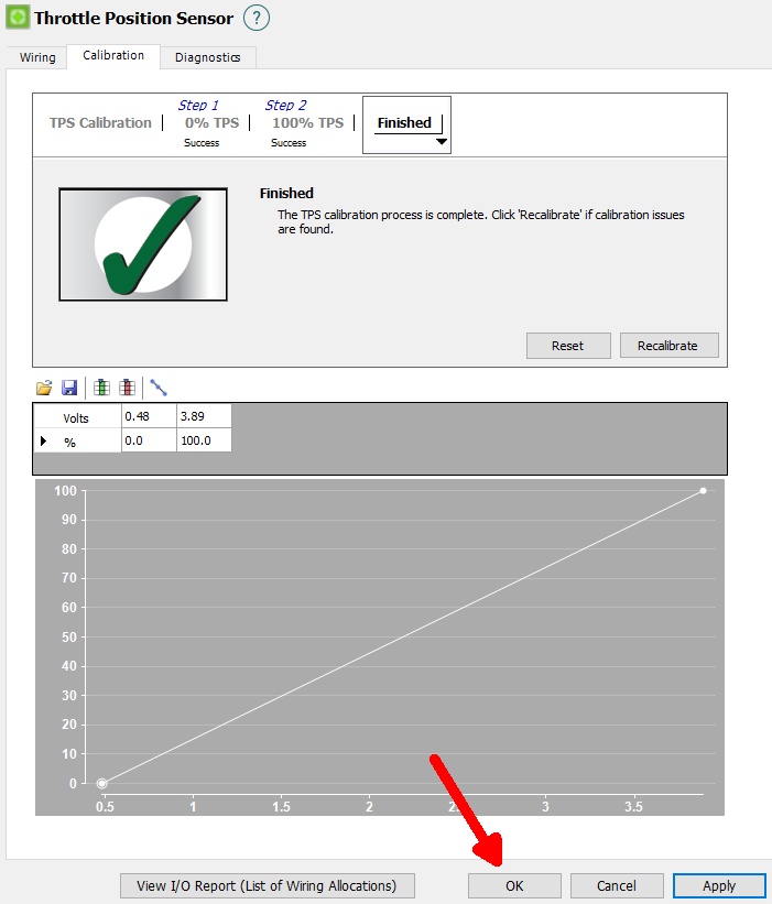
Related Articles
Throttle Position Sensor input
The throttle position sensor is mounted to the throttle butterfly shaft to measure its rotation. A TPS is common on many late model engines and the Haltech sensor should attach with little or no modification. The throttle shaft must protrude from the ...Throttle Position Sensor
TPS Settings A Throttle Position Sensor (TPS) is required by the ECU for many purposes. It can be used for the primary load input for some applications. It is also used with Idle Control, Decel Cut, Transient Throttle, and many other functions. A TPS ...Drive By Wire Throttle Wiring
Drive by wire technology is supported by the Elite 2500 ECU's and requires wiring of an Electronic Throttle and Accelerator Pedal Position sensor. Wiring setup and connection allocation can be found within the function in the setup page. This wiring ...Throttle Position Sensor
A Throttle Position Sensor (TPS) is required by the Elite ECU for many purposes. It can be used for the load input for some application. It is also used with Idle Control, Decel Cut, Transient Throttle, and many other functions. A TPS is a powered ...Transient Throttle
What is Transient Throttle ? Transient Throttle is a fuel correction function used to compensate for an opening or closing throttle body. As the throttle is opened and air enters the inlet manifold there is a period of time where the manifold ...