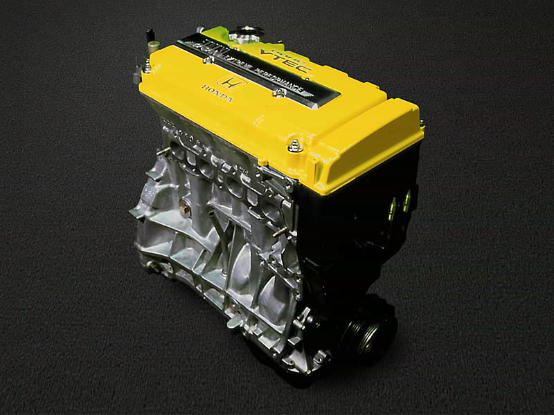
Honda / Acura B Series Engine
The B-Series engine was offered in Integras, Civics, Preludes, Accords, CRXs, Del Sols and CRVs. This engine had 28 different engine codes. The letter B is normally followed by two numbers to designate the displacement of the engine, another letter, and in US-spec engines, another number. Most Japanese engines do not have the final number. I.e. The B18C5 is a US Type R and the B18C is a JDM Type R.
Elite 1000 or 1500 with B-Series Plug N Play adapter (HT-140840) for the following vehicles:
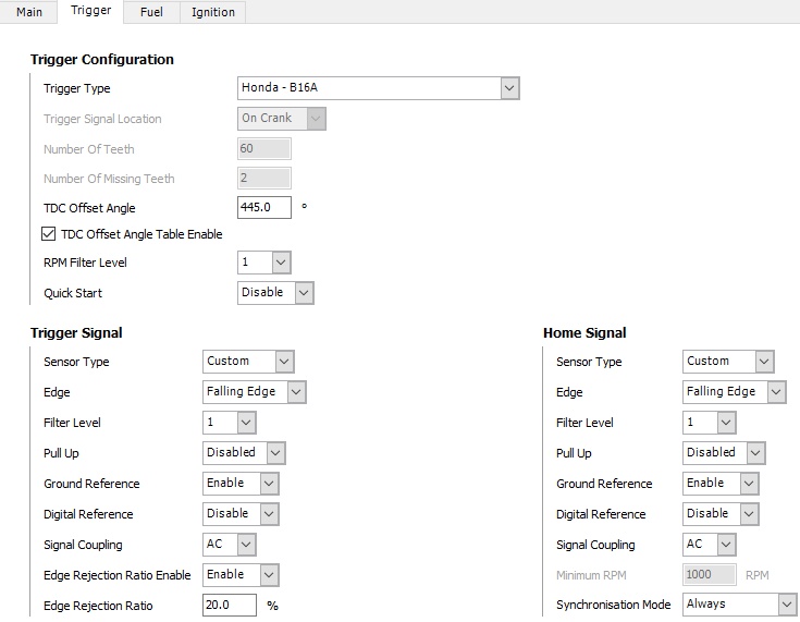
Trigger System
Trigger Configuration
General Information
| Haltech Elite Series Setting | Value |
Number of Cylinders | 4 |
Capacity | 1.6L, 1.7L, 1.8L, 2.0L |
Firing Order | 1-3-4-2 |
Engine Type | Piston 4 - Stroke |
Injection Mode | Sequential |
Number of Inj | 4 |
Inj Flow/Size | 235cc - 240cc |
Inj Current Setting | Low |
Ignition Mode | Distributor | Direct when Upgraded to K-Coils |
Ignition Edge | Distributor Rising | K-Coils Falling |
Ignition Dwell Mode | Constant Charge |
Trigger Tooth Pattern | 24 common or 16 |
Home Tooth Pattern | 1 |
ESP Trigger Pattern | Honda - B Engine |
TDC Angle | ~445 (movable distributor) |
Trigger Sensor Type | Reluctor |
Trigger Sensor Edge | Falling |
Trigger Filter Level | 0 |
Trigger Pullup | - |
Trigger Ground Ref | Disabled |
Home Sensor Type | Reluctor |
Home Sensor Type | Falling |
Home Filter Level | 0 |
Home Pull-up | - |
Home Ground Ref | Disabled |
Home Min RPM | - |
Quick Start | Disabled |
Notes | The trigger is commonly upgraded to T1. This trigger places 12 Crank and 1 Home Magnet on the Exhaust Cam Gear and uses a Dual Channel Hall Effect sensor (~TDC 490) | Generic - Multi-tooth - Single Tooth Home | On Cam | |
Elite 1000 or 1500 with B-Series Plug N Play adapter (HT-140840) for the following vehicles:
| ECU Code (Middle 3 Characters) | Vehicle (Some vehicles are not B-series, may use Engine Harness) |
P05 | 92-95 Civic CX |
P06 | 92-95 Civic DX |
P07 | 92-95 Civic VX |
P08 | 92-95 Civic D15 JDM |
P0A | 94-95 Accord EX |
P13 | 93-95 Prelude Vtec |
P14 | 93-95 Prelude Si (Non-Vtec) |
P27 | 92-95 Civic EG JDM SOHC 1.6l |
P28 | 92-95 Civic Si/EX |
P30 | 92-95 DelSol DOHC Vtec Si/EG Sir |
P61 | 92-93 Integra GSR |
P72 | 94-95 Integra GSR |
P74/75 | 92-95 Integra LS/GS |
Sensor Information
Trigger System
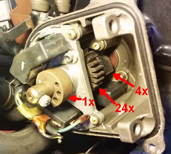
The B-series engines use a Distributor that has the trigger system. Early models have a 16x tooth pattern however most models have 24x teeth and Honda refer to this as the CKP sensor. There is a second trigger system with just 4x teeth that is used by Honda purely for engine starting that is not used by Haltech ECUs, and they refer to this as the TDC Sensor. For engine sync there is a 1x tooth pickup that is referred to as the CYP sensor.
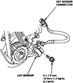
Some models have a crank trigger (CKF - Crank Fluctuation) with 12x teeth but still use a distributor. This can be used in place of the 24x pickup for more accurate ignition timing and is highly recommended. Trigger Configuration settings remain the same.
Trigger Configuration
The same trigger configuration is used for B16A and B18C. You can simply change the Trigger Type between the two.
Cylinder Identification Sensor Location
Distributor
All sensors inside the distributor are Reluctor Sensors.
| Distributor Pin | Sensor | Haltech Color | Haltech Output | Elite 550 / 750 | Elite 1000-2500 |
1 | Ignition Input Signal | Yellow / Black | Ignition Output #1 | 3 | A3 |
2 | CKP P | Yellow | Trigger (+VE) | 31 | B1 |
3 | TDC + (4 Events | Not Used) | - | |||
4 | CYP P | Yellow | Home (+VE) | 32 | B2 |
5 | CKP M | Green | Trigger (-VE) | 33 | B5 |
| 6 | CYP M | Green | Home (-VE) | 34 | B6 |
7 | TDC - (Not Used) | - | |||
8 | Engine Speed (tacho) | ||||
9 | Ignition Input 12v Switched | Red/ Yellow | 6 Circuit Fust Block (Ignition Relay) |
Ignition System
The ignition coil is incorporated in the distributor along with the igniter module. The ECU controls the dwell time so the configuration should be set to Constant Charge. What is unique is that these igniters use a RISING output edge from the ECU. For wiring see the Trigger system above.
Dwell
Throttle Position Sensor (TPS)
TPS Pin | Function | Haltech Color | Elite 550 / 750 | Elite 1000-2500 |
1 | Signal Ground | Black / White | 11 | B14 / B15 / B16 |
2 | TPS | White | 14 | A14 |
3 | 5v Supply | Orange | 9 | A9 |
MAP Sensor
MAP Pin | Function | Haltech Color | Elite 550 / 750 | Elite 1000-2000 |
1 | 5v Supply | Orange | 9 | A9 |
2 | MAP | Yellow | 15 | A15 |
3 | Signal Ground | Black / White | 11 | B14/ B15 / B16 |
Vehicle Speed Sensor
VSS Pin | Function | Elite ECU |
1 | Ground | - |
2 | Switched 12v | - |
3 | VSS | Any Available SPI or DPI |
Coolant Temperature Sensor (TW)
The Coolant Temperature Sensor for the ECU is called the TW sensor- located on end of head- This sensor is not polarity dependent.
Note: The coolant Temp Sensor from the "Sensor Location" image above is labeled TW. The Single wire sensor labeled Coolant Temp connects to the factory dash gauge.
TW Pin | Function | Haltech Color | Elite 550 / 750 | Elite 1000-2000 |
1 (Red/White) | Coolant Temp (Pull Up) | Violet | 30 | B4 |
2 (Green/Blue) | Signal Ground | Black/ White | 11 | B14/ B15/ B16 |
Coolant Temp Gauge Sender
Single wire connector by the distributor. This wire runs directly to the factory gauge.
Fan Switch
A two-wire sensor located at the Thermostat. This switch grounds the thermofan relay above 196-203F and opens the circuit (off) bellow 181 -189F. The Thermofan function can be used in place of this switch.
Air Temp
The sensor is commonly upgraded to an open body sensor similar to HT-010204 due to the slow response time of the factory AIT.
A two-wire sensor located on the Intake Manifold. This sensor is not polarity dependent. Caution: this connector is the same as the Idle Air Control Valve. If the IAC is connected the sensor will fail.
AIT Pin | Function | Haltech Color | Elite 550 / 750 | Elite 1000-2000 |
1 | Air Temp (Pull Up) | Gray | 29 | B3 |
2 | Signal Ground | Black/ White | 11 | B14/ B15/ B16 |
Alternator
| B (Large Lug) | Connect to Battery Positive |
C (Control) | The voltage regulator sends a voltage to the ECM
through the C circuit. Holding this circuit high (8v) to signal the
high output mode or it pulls the voltage low to signal the low output mode. |
FR (Field Reference) | Used to inform the ECU of charging mode (In High Output Idel RPM can be increased). The ECM sends 5V to the voltage regulator
through the FR circuit. When the field rotor is on, the voltage regulator will pull the voltage down and when the
field rotor is off it will hold the voltage high |
IG ( Ignition) | Battery Power when Key is on |
L ( Lamp) | Early Models: directly
provided ground for the warning lamp if a problem was present. If everything was in spec, the voltage regulator
removed the ground by providing positive source voltage on the L circuit. Late models: the
ECM sends source voltage to the L circuit. If a problem occurs, the voltage regulator will pull the voltage on the L
circuit to ground. |
Notes: | During heavy electrical or mechanical loads (i.e., if the AC clutch
is engaged), the ECU will set the charging voltage to 14.4-14.9V
(high output mode); during startup and light electrical load
conditions, the ECM will set the charging voltage to 12.4-12.9V
(low output mode). The factory ECM does this by monitoring an Electrical Load detector. ESP can replicate this by setting up conditions. The ECM uses the low output mode
when the engine is starting or if all of the following parameters are met (otherwise it uses High Output mode):
|
Electrical Load Detector
Evap Solenoid
Pin | Function | Elite ECU |
1 | Switched Power when Key on | - |
2 | Evap | Available Output (Active Low) |
Dual Runner / Intake AIr Bypass (GSR + H22)
When the engine rpm is below 5,750, the IAB control solenoid valve is activated by the ECU (Active High). Intake air flows through the long intake path, to deliver more torque. At speeds above 5,750 the solenoid valve is deactivated allowing for less airflow resistance through the short intake path.
Pin | Function | Elite ECU |
1 | Dual Intake Runner | Available Output (Active High) |
2 | Switched Battery Power | - |
VTEC (Variable Valve Timing and Lift Electronic Control)
The VTEC system uses two (or occasionally three) camshaft profiles and hydraulically selects between profiles. It is distinctly different from standard VVT (variable valve timing) systems which change only the valve timings and do not change the camshaft profile or valve lift in any way.
The "Cam Control Switched" function can be used to control the VTEC solenoid. At the switch point, a solenoid is activated that allows oil pressure from a spool valve to operate a locking pin which binds the High Lift Rocker. The oil pressure flows past this rocker, essentially creating a small oil passage leak. On average, oil pressure drops 15psi. Vtec should never be active at low RPM due to the loss of oil pressure. Typically Vtec should activate above 4500+ rpm.
Pin | Function | Elite ECU |
1 | Cam Control Switched | Stepper or DBW (High Side Output) |
Vtec Pressure Switch
On some applications, a Vtec pressure switch is used to monitor Oil pressure. If the pressure is not adequate, Vtec will not engage. Haltech ECUs do no require this switch or condition to activate Vtec. This switch completes a circuit to ground when active.
Pin | Elite ECU |
1 | AVI or Spi | Pulled to ground | Pull Up |
2 | Thermostat Ground |
Idle Control (IACV)
BAC Two-wire signal available from any Elite ECU.
IAC Pin | Function | Elite ECU |
1 (Blue / Black) | Idle Control | Available Output (Low Side) |
2 (Yellow / Black) | 12v Ignition Power | - |
Steering Pressure Switch (Vehicles with Power Steering)
Switch to the ground when pressure is on the steering rack. This can be used to increase the target idle (Duty Cycle)
-Any available Inputs (Pull Up recommended)
Pin | Function | Elite ECU |
1 | Power Steering Switch | Available Input (Pulled to Ground Active) |
OEM ECU
Related Articles
Honda K Series Engine
The Honda K-series engine is a line of four-cylinder four-stroke car engine introduced in 2001. The K-series engines are equipped with DOHC valvetrains and use roller rockers to reduce friction. The engines use a coil-on-plug, distributorless ...What’s So Special About Honda’s K-series
Honda’s contribution to motorsport and the JDM performance scene is unquestionable and today we’re going to take a closer look at what is arguably the most popular “modified” Honda engine – the K-series. Once upon a time in Japan…. Let’s start with a ...Nexus Plug-in ECU - Honda EP3 and DC5
Congratulations on your purchase of a Nexus Honda EP3 / Honda DC5 Plug-in ECU. This vehicle-specific product allows you to seamlessly integrate a Nexus ECU into your vehicle without the complexity of wiring. With this hassle-free solution, you can ...LY7 LE0 Alloytec Engine
Information on the GM LY7 High Feature Alloytec V6 engine. It will be referred to in this guide as the Alloytec. Haltech ECU Options The Elite 2000 can be used without DBW, the Elite 2500 is required with DBW. General Information Cylinders 6 ...VTEC Magic – MCM Mini Revisited
This little green Mini is one of Mighty Car Mods’ most enduring and popular builds. In its original guise, it was powered by a 1275cc, Siamese port engine supplemented with a belt-driven supercharger. Fast forward a couple of years and the guys ...