R18 Engine
Information on the Honda R18 engine
Haltech ECU Options
The Elite 1500 and 2500 are suitable for this engine.
General Information
| Cylinders | 4 |
| Displacement | 1799 cc / 109.8 ci |
| Firing Order | 1,3,4,2 |
CAN
This vehicles uses CAN bus for various devices throughout the vehicle. This can include the dashboard, ABS, and Body Control. Haltech does NOT support this CANbus system.
Model Variants
There are a number of variants of the Honda R18 engine. All are listed as being SOHC with i-VTEC
R18A1
10.5:1 compression, 6900rpm limit, Exhaust manifold is intergrated into the cylinder head
R18A2
7150rpm limit
R18Z1
10.6:1 compression
R18Z4
Balance shaft added
R18Z6
No listed differences
R18Z9
No listed differences
Common Models
MY06-on Civic
MY07-09 FR-V
MY08-15 City
MY07-14 Stream
MY13-17 Jade
MY16-on HR-V
Sensor Information
Trigger System
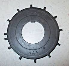
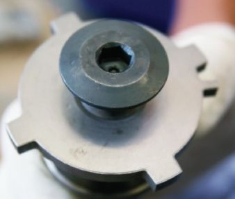
The R18 uses a crank sensor and a cam sensor. The crank trigger has 12x teeth plus 1x extra tooth used for crank sync. The cam sensor is used for engine sync, and for iVTEC cam positioning. All sensors are Hall Effect.
Crank Trigger

Cam Trigger


Crank Sensor
A Hall Effect crank position sensor is used.
| Pin | Description | Haltech Connection (Trigger 4-core) |
| 1 | 12V+ Switched | 12V+ (Red) |
| 2 | Signal | Trigger + (Yellow) |
| 3 | Signal Ground | Signal Ground (Blue) |
Cam Sensor
A Hall Effect cam sensor is used.
Hall Effect Wiring (UNVERIFIED)
| Pin | Description | Haltech Connection (Home 4-core) |
| 1 | 12V+ Switched | 12V+ (Red) |
| 2 | Signal | Home + (Yellow) |
| 3 | Signal Ground | Signal Ground (Blue) |
Ignition Coils and Igniter
The R18 engine uses Direct Fire with an ignition coil per spark plug. The coils have an internal igniter module and are wired directly to the ECU.
Settings are Constant Charge with a Falling edge. Selecting incorrect settings will damage the coil and possibly the ECU.
| Pin | Description | Haltech Connection |
| 1 | ECU Signal | Ignition Output |
| 2 | Ground to Cylinder Head | --- |
| 3 | 12V+ Switched | --- |
Dwell
DBW Throttle System
This engine uses a single Drive By Wire throttle body.
DBW Throttle Wiring
| Pin | Description | Haltech Connection |
| 1 | TPS 1 | AVI-2 (Orange/Black |
| 2 | 5V+ | 5V+ (Orange) |
| 3 | TPS2 | AVI-3 (Orange/Red) |
| 4 | Signal Ground | Signal Ground (Black/White) |
5 | Motor + | DBW1 (Brown/Black) |
6 | Motor - | DBW2 (Brown/Red) |
DBW Accelerator Pedal Position Sensors Connection
| Pin | Description | Haltech Connection |
| 1 | Signal 1 | AVI-4 (Orange/Yellow) |
| 2 | Signal Ground 1 | Signal Ground (Black/White) |
| 3 | 5V 1 | 5V+ (Orange) |
| 4 | Signal 2 | AVI-5 (Orange/Green) |
| 5 | Signal Ground 2 | Signal Ground (Black/White) |
| 6 | 5V2 | 5V+ (Orange) |
MAP Sensor
This vehicle comes with a MAP sensor.
| Pin | Description | Haltech Connection |
| 1 | 5V+ | 5V+ (orange) |
| 2 | Signal | Spare AVI (AVI-9 Yellow) |
| 3 | Signal Ground | Signal Ground (black/white) |
If preferred you can use the internal MAP sensor that comes with your ECU. For higher boost levels an external MAP sensor should be used instead, connected to a spare AVI.
MAF Sensor
Although most users of Haltech ECUs will be deleting the MAF, it is possible to use a MAF if you prefer.
| Pin | Description | Haltech Connection |
| 1 | 12V+ Switched | --- (grey/red in loom) |
| 2 | VGP MAF Signal | Spare AVI |
| 3 | VGM MAF Ground | Signal Ground (Black/White) |
| 4 | Inlet Air Temp Signal | Spare AVI (AVI-7 Grey with pullup enabled) |
| 5 | Air Temp Ground | Signal Ground (Black/White) |
Variable Cams Switched (SOHC i-VTEC)
This engine comes with an On/Off switched variable cam system. Under light load cruising conditions a different intake cam lobe is used with very retarded inlet close timing. Together with a different throttle map that runs more throttle opening under these conditions, the pumping losses of the engine are reduced and as such fuel economy is considerably improved. This is not designed as a power-adding device, it is purely for fuel economy. Due to the intricate nature of regulating engine torque under these conditions it is not currently something that can be done with a Haltech Elite.
Dual Intake Length
This engine has a variable intake length system. This is supported by the Haltech Elite ECU range with the Dual Intake Runner function.
Idle Control
This engine uses the Drive By Wire Throttle to control idle speed.
Coolant Temperature
Wiring is not polarity sensitive
| Pin | Haltech Connection |
| 1 | Any Spare AVI* |
| 2 | Signal Ground |
An AVI with a selectable Pullup should be used. If not and external 1k pullup to 5V should be connected.
Air Temp
An Inlet Air Temperature Sensor is incorporated in the MAF Sensor on this engine. See the MAF Sensor section for wiring information. If the MAF has been deleted a replacement Air Temperature Sensor should be installed in the inlet as close as possible to the vacuum source for the MAP sensor. The Haltech HT-010206 is suitable for this.
Haltech HT-010206 Air Temperature Sensor
Wiring is not polarity sensitive.
| Pin | Haltech Connection |
| 1 | Any Spare AVI* |
| 2 | Signal Ground |
An AVI with a selectable Pullup should be used. If not and external 1k pullup to 5V should be connected.
Knock Sensor
This engine comes with an older resonant style knock sensor. These are known to be unreliable and can give misleading information on engines that are modified from standard. For accurate knock control a donut style non-resonant sensor should be used, such as the Haltech HT-011100.
Haltech HT-011100 Knock Sensor
| Pin | Haltech Connection |
| 1 | Knock Signal |
| 2 | Signal Ground |
O2 Sensors
This engine has Narrow Band O2 sensors. Although they can be used for light load tuning for Lambda 1.0, they cannot be used for tuning under power.
Adding a Haltech Single-Channel Wideband WB1 Kit (highly recommended)
For correct operation a Haltech WB1 kit is highly recommended for this application, with the provided 4.9 sensors replacing the pre-cat sensors. Sensors use a 22mm socket or spanner to remove and replace.
Injector Data
Flow
The injector flow rate is measured with the injectors held wide open at 100% duty. For fuel systems with a fixed regulator pressure (often returnless systems) that is not referenced to manifold pressure the flow needs to be mapped over Manifold Pressure for accurate tuning.
Injector Flow: 185 cc/min
Dead Time
When an injector is commanded to open for a certain amount of time, the dead time is the amount of time the injector is not actually open during this period. It covers the time to energise the solenoid and begin to open and the time to close as well. There are also transient periods during which the injector is opening and closing where fuel flow is not at full capacity so this lost peak flow period is also taken into account.
OEM ECU Information
Location
The ECU is located near the battery
ECU Pinout
Related Articles
Nexus Plug-in ECU - Nissan Skyline R32/R33/R34 GT-R
Overview Congratulations on your purchase of a Nexus Plug-in ECU for a Nissan Skyline R32/R33/R34 GT-R! This vehicle-specific product allows you to seamlessly integrate a Nexus ECU into your vehicle without the complexities of wiring. With this ...LF (MZR) Engine
Information on the Mazda LF-VE 2.0L Engine. This is refered to as an MZR engine and is found in the NC MX5 Miata. They are also commonly referred to as a Ford Duratec engine, which differs from the early Zetec variants from Ford that were also ...RB20/25/26 Engine
The RB series of engines are among the most popular and desirable engines in today's enthusiast society. There is no other engine that sounds quite like a twin cam RB. They are known for a power-band that is smooth and increases as it progresses ...Honda / Acura B Series Engine
The B-Series engine was offered in Integras, Civics, Preludes, Accords, CRXs, Del Sols and CRVs. This engine had 28 different engine codes. The letter B is normally followed by two numbers to designate the displacement of the engine, another letter, ...Engine Functions
This page is used to enable and disable any Engine Function nodes in the Navigation Tree. Function names can be clicked on to navigate to that functions relevant tree node. Any errors will be highlighted in red for your attention.